This article is about the device. For the New Zealand band, see Dimmer (band). For the hamlet in England, see Dimmer, Somerset.
A dimmer is a device connected to a light fixture and used to lower the brightness of the light. By changing the voltage waveform applied to the lamp, it is possible to lower the intensity of the light output. Although variable-voltage devices are used for various purposes, the term dimmer is generally reserved for those intended to control light output from resistive incandescent, halogen, and (more recently) compact fluorescent lamps (CFLs) and light-emitting diodes (LEDs). More specialized equipment is needed to dim fluorescent, mercury-vapor, solid-state, and other arc lighting.
Dimmers range in size from small units the size of domestic light switches to high-power units used in large theatrical or architectural lighting installations. Small domestic dimmers are generally directly controlled, although remote control systems (such as X10) are available. Modern professional dimmers are generally controlled by a digital control system like DMX or DALI. In newer systems, these protocols are often used in conjunction with Ethernet.
In the professional lighting industry, changes in intensity are called «fades» and can be «fade up» or «fade down». Dimmers with direct manual control had a limit on the speed they could be varied at but this problem has been largely eliminated with modern digital units (although very fast changes in brightness may still be avoided for other reasons like lamp life).
Modern dimmers are built from semiconductors instead of variable resistors, because they have higher efficiency. A variable resistor would dissipate power as heat and acts as a voltage divider. Since semiconductor or solid-state dimmers switch quickly between a low resistance «on» state and a high resistance «off» state, they dissipate very little power compared with the controlled load.
Most recently, software programmable internal dimmers can use signals from the same switch that turns lights on and off to control dimming. No dedicated external dimmer is needed. A simple communications protocol, such as Blink’n’Dim, delivers dimming commands via the power line. They enable computer control via networked switches, but do not require it. Their cost is about the same as the older «dimmability» circuitry that they replace in LED bulbs, fixtures or drivers.
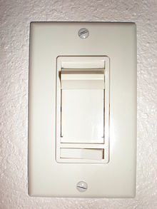
A residential-type dimmer switch with sliding knob to change brightness. The device is small enough to fit into a regular wall box provided for a switch.
History[edit]
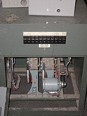
Early dimmers were directly controlled through the manual manipulation of large dimmer panels. This required all power to come through the lighting control location, which could be inconvenient, inefficient and potentially dangerous for large or high-powered systems, such as those used for stage lighting.
In 1896, Granville Woods patented his «Safety Dimmer», which greatly reduced wasted energy by reducing the amount of energy generated to match desired demand rather than burning off unwanted energy.[1]
In 1959, Joel S. Spira, who would found the Lutron Electronics Company in 1961, invented a dimmer based on a then-new solid state switching device called a Silicon Controlled Rectifier or SCR. This small device allowed the dimmer to be installed in a standard electrical wall box while saving energy.[2][3]
In 1966, Eugene Alessio patented a light bulb socket adapter for adjusting a light level on a single light bulb using a triac. To house this device, he decided on a 2-inch round device with one end capable of being screwed into a light bulb socket and the other end able to receive a light bulb.[4]
When solid-state dimmers came into use, analog remote control systems (such as 0-10 V lighting control systems) became feasible. The wire for the control systems was much smaller (with low current and lower danger) than the heavy power cables of previous lighting systems. Each dimmer had its own control wires, resulting in many wires leaving the lighting control location.
More recent digital control protocols such as DMX512, DALI, or one of the many Ethernet-based protocols like Art-Net, ETCnet, sACN, Pathport, ShowNet or KiNET[5] enable the control of a large number of dimmers (and other stage equipment) through a single cable.
Types of dimmer[edit]
Rheostat dimmer[edit]
Dimmers based on rheostats were inefficient since they would dissipate a significant portion of the power rating of the load as heat. They were large and required plenty of cooling air. Because their dimming effect depended a great deal on the total load applied to each rheostat, the load needed to be matched fairly carefully to the power rating of the rheostat. Finally, as they relied on mechanical control they were slow and it was difficult to change many channels at a time.
Salt water dimmer[edit]
Early examples of a rheostat dimmer include a salt water dimmer or liquid rheostat; the liquid between a movable and fixed contact provided a variable resistance. The closer the contacts to each other, the more voltage was available for the light. Salt water dimmers required regular addition of water and maintenance due to corrosion; exposed parts were energized during operation, presenting a shock hazard.[6][unreliable source?]
Coil-rotation transformer[edit]
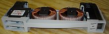
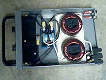
Two 6000 watt motor driven autotransformer dimmers, used for theatre auditorium lighting
The coil-rotation transformer used a fixed-position electromagnet coil in conjunction with a variable-position coil to vary the voltage in the line by varying the alignment of the two coils. Rotated 90 degrees apart, the secondary coil is affected by two equal but opposite fields from the primary, which effectively cancel each other out and produce no voltage in the secondary.
These coils resembled the standard rotor and stator as used in an electric motor, except that the rotor was held against rotation using brakes and was moved to specific positions using high-torque gearing. Because the rotor did not ever turn a complete revolution, a commutator was not required and long flexible cables could be used on the rotor instead.
Autotransformer dimmer[edit]
Variable autotransformers (trade name «Variac») were then introduced. While they are still nearly as large as rheostat dimmers, which they closely resemble, they are relatively efficient devices. Their voltage output, and so their dimming effect, is largely independent of the load applied so it was far easier to design the lighting that would be attached to each autotransformer channel. Remote control of the dimmers was still impractical, although some dimmers were equipped with motor drives that could slowly and steadily reduce or increase the brightness of the attached lamps. Autotransformers have fallen out of use for lighting but are used for other applications.
However, there are certain lighting scenarios in which autotransformers are still a desirable solution (as of 2021). For instance, the control room of an audio recording studio may require an extremely strict limit for electromagnetic interference. In comparison with solid-state dimmers, the conducted emissions produced by autotransformers are effectively zero.[citation needed]
Solid-state dimmer[edit]

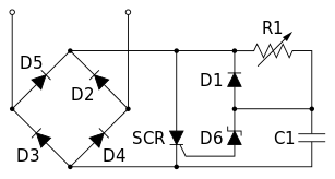
An electrical schematic for a typical SCR-based light dimmer
Solid-state, or semiconductor, dimmers were introduced to solve some of these problems. Semiconductor dimmers switch on at an adjustable time (phase angle) after the start of each alternating-current half-cycle, thereby altering the voltage waveform applied to lamps and so changing its RMS effective value. Because they switch instead of absorbing part of the voltage supplied, there is very little wasted power. Dimming can be almost instantaneous and is easily controlled by remote electronics. This development also made it possible to make dimmers small enough to be used in place (within the pattress) of normal domestic light switches.
The switches generate some heat during switching and can also cause radio-frequency interference.[7] Inductors or chokes are used as part of the circuitry to suppress this interference. When the dimmer is at 50% power, the switches are switching their highest voltage (>325 V in Europe) and the sudden surge of power causes the coils on the inductor to move, creating a buzzing sound associated with some types of dimmer; this same effect can be heard in the filaments of the incandescent lamps as «singing». The suppression circuitry might be insufficient to prevent buzzing to be heard on sensitive audio and radio equipment that shares the mains supply with the lighting loads. In this case, special steps must be taken to prevent this interference.[8] European dimmers must comply with relevant EMC legislation requirements; this involves suppressing the emissions described above to limits described in EN55104.
In the electrical schematic shown, a typical light dimmer based on a silicon-controlled rectifier (SCR) dims the light through phase-angle control. This unit is wired in series with the load. Diodes (D2, D3, D4 and D5) form a bridge, which generates pulsed DC. R1 and C1 form a circuit with a time constant. As the voltage increases from zero (at the start of every halfwave) C1 charges up. When C1 is able to make Zener diode D6 conduct and inject current into the SCR, the SCR fires. When the SCR conducts, D1 discharges C1 through the SCR. The SCR shuts off when the current falls to zero and the supply voltage drops at the end of the half cycle, ready for the circuit to start work on the next half cycle. This circuit is called a leading-edge dimmer or forward phase dimming. Leading-edge dimmers work well with incandescent lamps, but not with all types of LED lamps.[9]

Waveform of the output voltage of a thyristor dimmer set for 60 volts RMS output, with 120 V input. The red trace shows the output device switching on about 5.5 ms after the input (blue) voltage crosses zero. Switching the thyristor on earlier in each half cycle gives a higher output voltage and brighter lights.
Dimmers based on insulated-gate bipolar transistors (IGBTs) do away with most of the noise present in TRIACs by chopping off the falling side of the sine wave. These circuits are called trailing-edge dimmers or reverse phase dimming and work well with LED lamps.[9]
An even newer, but still expensive technology is sine-wave dimming, which is implemented as a high-power switched-mode power supply followed by a filter.[10][11]
Control[edit]

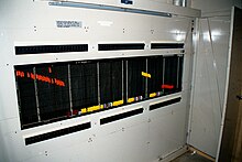
A dimmer rack containing 192 dimmers, with one dimmer per circuit. The black box at the upper left is a demultiplexer.

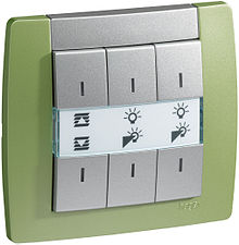
Dimmer in a residential application with RF-based remote control
Non domestic dimmers are usually controlled remotely by means of various protocols. Analogue dimmers usually require a separate wire for each channel of dimming carrying a voltage between 0 and 10 V. Some analogue circuitry then derives a control signal from this and the mains supply for the switches. As more channels are added to the system more wires are needed between the lighting controller and the dimmers.
In the late 70s, serial analogue protocols were developed. These multiplexed a series of analogue levels onto a single wire, with embedded clocking signal similar to a composite video signal (in the case of Strand Lighting’s European D54 standard, handling 384 dimmers) or separate clocking signal (in the case of the US standard AMX192).
Digital protocols, such as DMX512 have proved to be the answer since the late 80s. In early implementations a digital signal was sent from the controller to a demultiplexer, which sat next to the dimmers. This converted the digital signal into a collection of 0 to +10 V or 0 to −10 V signals which could be connected to the individual analogue control circuits.
Modern dimmer designs use microprocessors to convert the digital signal directly into a control signal for the switches. This has many advantages, giving closer control over the dimming, and giving the opportunity for diagnostic feedback to be sent digitally back to the lighting controller.
Some dimmers in residential applications are also equipped with a radio receiver to be used as wireless light switches which can be remotely controlled by a radio transmitter.[12]
Patching[edit]
Patching is the physical («hard patch») or virtual («soft patch») assignment to a circuit or channel for the purpose of control.
Hard patch[edit]
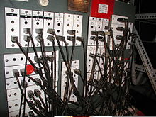
A telephone-type patch bay
Dimmers are usually arranged together in racks, where they can be accessed easily, and then power is run to the instruments being controlled. In architectural installations electricity is run straight from the dimmers to the lights via permanent wiring (this is called a circuit). They are hard run and cannot be changed.
However venues such as theatres demand more flexibility. To allow for changes for each show, and occasionally during shows, theatres sometimes install circuits run permanently to sockets around the theatre. Instead of these circuits going directly to the dimmer they are connected to a patch bay. A patch bay usually sits next to the dimmers enabling the dimmers to be connected to specific circuits via a patch cable. The patch bay may also enable many circuits to be connected to one dimmer and even series connection for low-voltage lamps. Also in some theatres individual cables are run directly from the light to dimmer. The assigned connections between the circuits (either at the patch bay or in the form of individual cables) and the dimmers is known as the mains or hard patch. This is most common in older theatres, and on a tour where dimmers will be brought in by the touring company.
Soft patch[edit]
Most modern fixed installations do not have patch bays; instead they have a dimmer-per-circuit, and patch dimmers into channels using a computerised control console’s Soft Patch.
Dimming curves[edit]
The design of most analogue dimmers meant that the output of the dimmer was not directly proportional to the input. Instead, as the operator brought up a fader, the dimmer would dim slowly at first, then quickly in the middle, then slowly at the top. The shape of the curve resembled that of the third quarter of a sine wave. Different dimmers produced different dimmer curves, and different applications typically demanded different responses.
Television often uses a «square law» curve, providing finer control in top part of the curve, essential to allow accurate trimming of the colour temperature of lighting. Theatrical dimmers tend to use a softer «S» or linear curve. Digital dimmers can be made to have whatever curve the manufacturer desires; they may have a choice between a linear relationship and selection of different curves, so that they can be matched with older analogue dimmers. Sophisticated systems provide user-programmable or nonstandard curves, and a common use of a nonstandard curve is to turn a dimmer into a «non-dim», switching on at a user defined control level.

Preheat[edit]
Switching high-intensity incandescent (filament) lamps to full power from cold can shorten their life dramatically, owing to the large inrush current that occurs. To reduce stress on the lamp filaments, dimmers may have a preheat function. This sets a minimum level, usually between 5% and 10%, which appears turned-off, but stops the lamp from cooling down too much. This also speeds up the lamp’s reaction to sudden bursts of power that operators of rock’n’roll-style shows appreciate. The opposite of this function is sometimes called top-set. This limits the maximum power supplied to a lamp, which can also extend its life.
In less advanced systems, this same effect is achieved by literally pre-heating (warming) the globes before an event or performance. This is usually achieved by slowly bringing the lights up to full (or usually 90-95%) power over a period of between 1/2 to 1 hour. This is as effective as a built-in preheat function.
Digital[edit]

Example of an «S» curve a lightboard can soft patch
Modern digital desks can emulate preheat and dimmer curves and allow a soft patch to be done in memory. This is often preferred as it means that the dimmer rack can be exchanged for another one without having to transfer complicated settings. Many different curves, or profiles can be programmed and used on different channels.
Rise time[edit]
One measure of the quality of a leading edge dimmer is the «rise time». The rise time in this context is the amount of time it takes for the cut part of the waveform to get from zero to the instantaneous output voltage. In the waveform above it is a measure of the slope of the almost vertical edge of the red trace. Typically it is measured in tens to hundreds of microseconds. A longer rise time reduces the noise of the dimmer and the lamp as well as extending the life of the lamp. A longer rise time also reduces the electromagnetic interference produced by the dimmer. Unsurprisingly, a longer rise time is more expensive to implement than a short one, this is because the size of choke has to be increased. Newer dimming methods can help minimize such problems.
See also[edit]
- Avolites
- Choke
- Compulite
- Derating
- Fluorescent lamp
- Heat sink
- Home automation
- Infinite switch
- Lighting control console
- Potentiometer
- Wireless light switch
References[edit]
- ^ «Patent US569443 — Granville t».
- ^ «Lutron Electronics Donates Company History to National Museum of American History». 28 April 2010.
- ^ «Patent US3032688 — Dimming device».
- ^ «Patent US3452215 — Light bulb socket adapter».
- ^ «Open Lighting Architecture».
- ^ «Types of dimmer». Archived from the original on 2010-01-11. Retrieved 2010-01-21.
- ^ «Lutron Electronics, Inc». asia.lutron.com. Archived from the original on 2006-10-25.
- ^ http://www.lutron.com/TechnicalDocumentLibrary/360484.pdf[bare URL PDF]
- ^ a b «Can You Put LED Lights On a Dimmer?». Energy Today. November 14, 2017. Retrieved January 27, 2019.
- ^ «Strand Dimming Systems» (PDF). Archived from the original (PDF) on 2018-01-02.
- ^ «Dimming Methods». Archived from the original on 2014-10-16.
- ^ «How Do Lighting Controls Work?». HeathCo LLC. Archived from the original on 13 September 2014. Retrieved 6 September 2014.
- Bellman, Wilard F. (2001). Lighting the Stage. Art and Practice, Third Edition, Chapter 4 –The Control Console, Broadway Press, Inc., Louisville Kentucky, ISBN 0-911747-40-0,
- Van Goethem, Chris (2019). Fading Lights. Transitions in theatre lighting in a historical context In: Die Vierte Wand. Organ der Initiative TheaterMuseum Berlin. 009/2019, p. 128–139 (Online at Internet Archive)
- sound.whsites.net
External links[edit]
- Light dimmer circuits
- Dimmers, Switchbanks & Efficiency
This article is about the device. For the New Zealand band, see Dimmer (band). For the hamlet in England, see Dimmer, Somerset.
A dimmer is a device connected to a light fixture and used to lower the brightness of the light. By changing the voltage waveform applied to the lamp, it is possible to lower the intensity of the light output. Although variable-voltage devices are used for various purposes, the term dimmer is generally reserved for those intended to control light output from resistive incandescent, halogen, and (more recently) compact fluorescent lamps (CFLs) and light-emitting diodes (LEDs). More specialized equipment is needed to dim fluorescent, mercury-vapor, solid-state, and other arc lighting.
Dimmers range in size from small units the size of domestic light switches to high-power units used in large theatrical or architectural lighting installations. Small domestic dimmers are generally directly controlled, although remote control systems (such as X10) are available. Modern professional dimmers are generally controlled by a digital control system like DMX or DALI. In newer systems, these protocols are often used in conjunction with Ethernet.
In the professional lighting industry, changes in intensity are called «fades» and can be «fade up» or «fade down». Dimmers with direct manual control had a limit on the speed they could be varied at but this problem has been largely eliminated with modern digital units (although very fast changes in brightness may still be avoided for other reasons like lamp life).
Modern dimmers are built from semiconductors instead of variable resistors, because they have higher efficiency. A variable resistor would dissipate power as heat and acts as a voltage divider. Since semiconductor or solid-state dimmers switch quickly between a low resistance «on» state and a high resistance «off» state, they dissipate very little power compared with the controlled load.
Most recently, software programmable internal dimmers can use signals from the same switch that turns lights on and off to control dimming. No dedicated external dimmer is needed. A simple communications protocol, such as Blink’n’Dim, delivers dimming commands via the power line. They enable computer control via networked switches, but do not require it. Their cost is about the same as the older «dimmability» circuitry that they replace in LED bulbs, fixtures or drivers.
A residential-type dimmer switch with sliding knob to change brightness. The device is small enough to fit into a regular wall box provided for a switch.
History[edit]
Early dimmers were directly controlled through the manual manipulation of large dimmer panels. This required all power to come through the lighting control location, which could be inconvenient, inefficient and potentially dangerous for large or high-powered systems, such as those used for stage lighting.
In 1896, Granville Woods patented his «Safety Dimmer», which greatly reduced wasted energy by reducing the amount of energy generated to match desired demand rather than burning off unwanted energy.[1]
In 1959, Joel S. Spira, who would found the Lutron Electronics Company in 1961, invented a dimmer based on a then-new solid state switching device called a Silicon Controlled Rectifier or SCR. This small device allowed the dimmer to be installed in a standard electrical wall box while saving energy.[2][3]
In 1966, Eugene Alessio patented a light bulb socket adapter for adjusting a light level on a single light bulb using a triac. To house this device, he decided on a 2-inch round device with one end capable of being screwed into a light bulb socket and the other end able to receive a light bulb.[4]
When solid-state dimmers came into use, analog remote control systems (such as 0-10 V lighting control systems) became feasible. The wire for the control systems was much smaller (with low current and lower danger) than the heavy power cables of previous lighting systems. Each dimmer had its own control wires, resulting in many wires leaving the lighting control location.
More recent digital control protocols such as DMX512, DALI, or one of the many Ethernet-based protocols like Art-Net, ETCnet, sACN, Pathport, ShowNet or KiNET[5] enable the control of a large number of dimmers (and other stage equipment) through a single cable.
Types of dimmer[edit]
Rheostat dimmer[edit]
Dimmers based on rheostats were inefficient since they would dissipate a significant portion of the power rating of the load as heat. They were large and required plenty of cooling air. Because their dimming effect depended a great deal on the total load applied to each rheostat, the load needed to be matched fairly carefully to the power rating of the rheostat. Finally, as they relied on mechanical control they were slow and it was difficult to change many channels at a time.
Salt water dimmer[edit]
Early examples of a rheostat dimmer include a salt water dimmer or liquid rheostat; the liquid between a movable and fixed contact provided a variable resistance. The closer the contacts to each other, the more voltage was available for the light. Salt water dimmers required regular addition of water and maintenance due to corrosion; exposed parts were energized during operation, presenting a shock hazard.[6][unreliable source?]
Coil-rotation transformer[edit]
Two 6000 watt motor driven autotransformer dimmers, used for theatre auditorium lighting
The coil-rotation transformer used a fixed-position electromagnet coil in conjunction with a variable-position coil to vary the voltage in the line by varying the alignment of the two coils. Rotated 90 degrees apart, the secondary coil is affected by two equal but opposite fields from the primary, which effectively cancel each other out and produce no voltage in the secondary.
These coils resembled the standard rotor and stator as used in an electric motor, except that the rotor was held against rotation using brakes and was moved to specific positions using high-torque gearing. Because the rotor did not ever turn a complete revolution, a commutator was not required and long flexible cables could be used on the rotor instead.
Autotransformer dimmer[edit]
Variable autotransformers (trade name «Variac») were then introduced. While they are still nearly as large as rheostat dimmers, which they closely resemble, they are relatively efficient devices. Their voltage output, and so their dimming effect, is largely independent of the load applied so it was far easier to design the lighting that would be attached to each autotransformer channel. Remote control of the dimmers was still impractical, although some dimmers were equipped with motor drives that could slowly and steadily reduce or increase the brightness of the attached lamps. Autotransformers have fallen out of use for lighting but are used for other applications.
However, there are certain lighting scenarios in which autotransformers are still a desirable solution (as of 2021). For instance, the control room of an audio recording studio may require an extremely strict limit for electromagnetic interference. In comparison with solid-state dimmers, the conducted emissions produced by autotransformers are effectively zero.[citation needed]
Solid-state dimmer[edit]
An electrical schematic for a typical SCR-based light dimmer
Solid-state, or semiconductor, dimmers were introduced to solve some of these problems. Semiconductor dimmers switch on at an adjustable time (phase angle) after the start of each alternating-current half-cycle, thereby altering the voltage waveform applied to lamps and so changing its RMS effective value. Because they switch instead of absorbing part of the voltage supplied, there is very little wasted power. Dimming can be almost instantaneous and is easily controlled by remote electronics. This development also made it possible to make dimmers small enough to be used in place (within the pattress) of normal domestic light switches.
The switches generate some heat during switching and can also cause radio-frequency interference.[7] Inductors or chokes are used as part of the circuitry to suppress this interference. When the dimmer is at 50% power, the switches are switching their highest voltage (>325 V in Europe) and the sudden surge of power causes the coils on the inductor to move, creating a buzzing sound associated with some types of dimmer; this same effect can be heard in the filaments of the incandescent lamps as «singing». The suppression circuitry might be insufficient to prevent buzzing to be heard on sensitive audio and radio equipment that shares the mains supply with the lighting loads. In this case, special steps must be taken to prevent this interference.[8] European dimmers must comply with relevant EMC legislation requirements; this involves suppressing the emissions described above to limits described in EN55104.
In the electrical schematic shown, a typical light dimmer based on a silicon-controlled rectifier (SCR) dims the light through phase-angle control. This unit is wired in series with the load. Diodes (D2, D3, D4 and D5) form a bridge, which generates pulsed DC. R1 and C1 form a circuit with a time constant. As the voltage increases from zero (at the start of every halfwave) C1 charges up. When C1 is able to make Zener diode D6 conduct and inject current into the SCR, the SCR fires. When the SCR conducts, D1 discharges C1 through the SCR. The SCR shuts off when the current falls to zero and the supply voltage drops at the end of the half cycle, ready for the circuit to start work on the next half cycle. This circuit is called a leading-edge dimmer or forward phase dimming. Leading-edge dimmers work well with incandescent lamps, but not with all types of LED lamps.[9]
Waveform of the output voltage of a thyristor dimmer set for 60 volts RMS output, with 120 V input. The red trace shows the output device switching on about 5.5 ms after the input (blue) voltage crosses zero. Switching the thyristor on earlier in each half cycle gives a higher output voltage and brighter lights.
Dimmers based on insulated-gate bipolar transistors (IGBTs) do away with most of the noise present in TRIACs by chopping off the falling side of the sine wave. These circuits are called trailing-edge dimmers or reverse phase dimming and work well with LED lamps.[9]
An even newer, but still expensive technology is sine-wave dimming, which is implemented as a high-power switched-mode power supply followed by a filter.[10][11]
Control[edit]
A dimmer rack containing 192 dimmers, with one dimmer per circuit. The black box at the upper left is a demultiplexer.
Dimmer in a residential application with RF-based remote control
Non domestic dimmers are usually controlled remotely by means of various protocols. Analogue dimmers usually require a separate wire for each channel of dimming carrying a voltage between 0 and 10 V. Some analogue circuitry then derives a control signal from this and the mains supply for the switches. As more channels are added to the system more wires are needed between the lighting controller and the dimmers.
In the late 70s, serial analogue protocols were developed. These multiplexed a series of analogue levels onto a single wire, with embedded clocking signal similar to a composite video signal (in the case of Strand Lighting’s European D54 standard, handling 384 dimmers) or separate clocking signal (in the case of the US standard AMX192).
Digital protocols, such as DMX512 have proved to be the answer since the late 80s. In early implementations a digital signal was sent from the controller to a demultiplexer, which sat next to the dimmers. This converted the digital signal into a collection of 0 to +10 V or 0 to −10 V signals which could be connected to the individual analogue control circuits.
Modern dimmer designs use microprocessors to convert the digital signal directly into a control signal for the switches. This has many advantages, giving closer control over the dimming, and giving the opportunity for diagnostic feedback to be sent digitally back to the lighting controller.
Some dimmers in residential applications are also equipped with a radio receiver to be used as wireless light switches which can be remotely controlled by a radio transmitter.[12]
Patching[edit]
Patching is the physical («hard patch») or virtual («soft patch») assignment to a circuit or channel for the purpose of control.
Hard patch[edit]
A telephone-type patch bay
Dimmers are usually arranged together in racks, where they can be accessed easily, and then power is run to the instruments being controlled. In architectural installations electricity is run straight from the dimmers to the lights via permanent wiring (this is called a circuit). They are hard run and cannot be changed.
However venues such as theatres demand more flexibility. To allow for changes for each show, and occasionally during shows, theatres sometimes install circuits run permanently to sockets around the theatre. Instead of these circuits going directly to the dimmer they are connected to a patch bay. A patch bay usually sits next to the dimmers enabling the dimmers to be connected to specific circuits via a patch cable. The patch bay may also enable many circuits to be connected to one dimmer and even series connection for low-voltage lamps. Also in some theatres individual cables are run directly from the light to dimmer. The assigned connections between the circuits (either at the patch bay or in the form of individual cables) and the dimmers is known as the mains or hard patch. This is most common in older theatres, and on a tour where dimmers will be brought in by the touring company.
Soft patch[edit]
Most modern fixed installations do not have patch bays; instead they have a dimmer-per-circuit, and patch dimmers into channels using a computerised control console’s Soft Patch.
Dimming curves[edit]
The design of most analogue dimmers meant that the output of the dimmer was not directly proportional to the input. Instead, as the operator brought up a fader, the dimmer would dim slowly at first, then quickly in the middle, then slowly at the top. The shape of the curve resembled that of the third quarter of a sine wave. Different dimmers produced different dimmer curves, and different applications typically demanded different responses.
Television often uses a «square law» curve, providing finer control in top part of the curve, essential to allow accurate trimming of the colour temperature of lighting. Theatrical dimmers tend to use a softer «S» or linear curve. Digital dimmers can be made to have whatever curve the manufacturer desires; they may have a choice between a linear relationship and selection of different curves, so that they can be matched with older analogue dimmers. Sophisticated systems provide user-programmable or nonstandard curves, and a common use of a nonstandard curve is to turn a dimmer into a «non-dim», switching on at a user defined control level.
Preheat[edit]
Switching high-intensity incandescent (filament) lamps to full power from cold can shorten their life dramatically, owing to the large inrush current that occurs. To reduce stress on the lamp filaments, dimmers may have a preheat function. This sets a minimum level, usually between 5% and 10%, which appears turned-off, but stops the lamp from cooling down too much. This also speeds up the lamp’s reaction to sudden bursts of power that operators of rock’n’roll-style shows appreciate. The opposite of this function is sometimes called top-set. This limits the maximum power supplied to a lamp, which can also extend its life.
In less advanced systems, this same effect is achieved by literally pre-heating (warming) the globes before an event or performance. This is usually achieved by slowly bringing the lights up to full (or usually 90-95%) power over a period of between 1/2 to 1 hour. This is as effective as a built-in preheat function.
Digital[edit]
Example of an «S» curve a lightboard can soft patch
Modern digital desks can emulate preheat and dimmer curves and allow a soft patch to be done in memory. This is often preferred as it means that the dimmer rack can be exchanged for another one without having to transfer complicated settings. Many different curves, or profiles can be programmed and used on different channels.
Rise time[edit]
One measure of the quality of a leading edge dimmer is the «rise time». The rise time in this context is the amount of time it takes for the cut part of the waveform to get from zero to the instantaneous output voltage. In the waveform above it is a measure of the slope of the almost vertical edge of the red trace. Typically it is measured in tens to hundreds of microseconds. A longer rise time reduces the noise of the dimmer and the lamp as well as extending the life of the lamp. A longer rise time also reduces the electromagnetic interference produced by the dimmer. Unsurprisingly, a longer rise time is more expensive to implement than a short one, this is because the size of choke has to be increased. Newer dimming methods can help minimize such problems.
See also[edit]
- Avolites
- Choke
- Compulite
- Derating
- Fluorescent lamp
- Heat sink
- Home automation
- Infinite switch
- Lighting control console
- Potentiometer
- Wireless light switch
References[edit]
- ^ «Patent US569443 — Granville t».
- ^ «Lutron Electronics Donates Company History to National Museum of American History». 28 April 2010.
- ^ «Patent US3032688 — Dimming device».
- ^ «Patent US3452215 — Light bulb socket adapter».
- ^ «Open Lighting Architecture».
- ^ «Types of dimmer». Archived from the original on 2010-01-11. Retrieved 2010-01-21.
- ^ «Lutron Electronics, Inc». asia.lutron.com. Archived from the original on 2006-10-25.
- ^ http://www.lutron.com/TechnicalDocumentLibrary/360484.pdf[bare URL PDF]
- ^ a b «Can You Put LED Lights On a Dimmer?». Energy Today. November 14, 2017. Retrieved January 27, 2019.
- ^ «Strand Dimming Systems» (PDF). Archived from the original (PDF) on 2018-01-02.
- ^ «Dimming Methods». Archived from the original on 2014-10-16.
- ^ «How Do Lighting Controls Work?». HeathCo LLC. Archived from the original on 13 September 2014. Retrieved 6 September 2014.
- Bellman, Wilard F. (2001). Lighting the Stage. Art and Practice, Third Edition, Chapter 4 –The Control Console, Broadway Press, Inc., Louisville Kentucky, ISBN 0-911747-40-0,
- Van Goethem, Chris (2019). Fading Lights. Transitions in theatre lighting in a historical context In: Die Vierte Wand. Organ der Initiative TheaterMuseum Berlin. 009/2019, p. 128–139 (Online at Internet Archive)
- sound.whsites.net
External links[edit]
- Light dimmer circuits
- Dimmers, Switchbanks & Efficiency
|
|
См. также Хор, димер. |
| В Википедии есть статья «диммер». |
Содержание
- 1 Русский
- 1.1 Морфологические и синтаксические свойства
- 1.2 Произношение
- 1.3 Семантические свойства
- 1.3.1 Значение
- 1.3.2 Синонимы
- 1.3.3 Антонимы
- 1.3.4 Гиперонимы
- 1.3.5 Гипонимы
- 1.4 Родственные слова
- 1.5 Этимология
- 1.6 Фразеологизмы и устойчивые сочетания
- 1.7 Перевод
- 1.8 Библиография
Русский[править]
| В Викиданных есть лексема диммер (L106165). |
Морфологические и синтаксические свойства[править]
| падеж | ед. ч. | мн. ч. |
|---|---|---|
| Им. | ди́ммер | ди́ммеры |
| Р. | ди́ммера | ди́ммеров |
| Д. | ди́ммеру | ди́ммерам |
| В. | ди́ммер | ди́ммеры |
| Тв. | ди́ммером | ди́ммерами |
| Пр. | ди́ммере | ди́ммерах |
ди́м—мер
Существительное, неодушевлённое, мужской род, 2-е склонение (тип склонения 1a по классификации А. А. Зализняка).
Корень: -диммер-.
Произношение[править]
- МФА: [ˈdʲimʲ(ː)ɪr]
Семантические свойства[править]
Значение[править]
- реостат для регулирования силы света лампы ◆ Простейшим вариантом диммера является переменный резистор, включенный последовательно с лампой.
Синонимы[править]
- светорегулятор
Антонимы[править]
Гиперонимы[править]
Гипонимы[править]
Родственные слова[править]
| Ближайшее родство | |
|
Этимология[править]
Происходит от англ. dimmer, от англ. dim «затемнять».
Фразеологизмы и устойчивые сочетания[править]
Перевод[править]
| Список переводов | |
|
Библиография[править]
- Шагалова Е. Н. Словарь новейших иностранных слов (конец XX — начало XXI вв.): более 3000 слов и словосочетаний. — М. : АСТ: Астрель, 2010. — 943, [1] с. — (Biblio). — ISBN 978-5-17-061488-2, ISBN 978-5-17-061488-2.
|
|
Для улучшения этой статьи желательно:
|
Ударение в слове «Диммер»
диммер
Слово «диммер» правильно пишется как «диммер», с ударением на гласную — и (1-ый слог).
Оцени материал
9 голосов, оценка 4.333 из 5
Поставить ударение в другом слове
1. реостат для регулирования силы света лампы
Все значения слова «диммер»
-
Каждый осветительный прибор должен быть снабжён диммером, чтобы яркость света всегда соответствовала вашему настроению.
-
Среди них полупроводниковый лазер с красным излучением, обычно называемый лазерным диодом (используемый в CD и DVD-плеерах и сотовых телефонах), квантовый полупроводниковый лазер (используется в волоконной оптике) и короткозамкнутый эмиттерный pnpn-переключатель (используемый в световых диммерах и электроинструментах).
-
Так она объясняла это себе, и даже не делала над собой усилия повернуть диммер дальше по часовой стрелке.
- (все предложения)
- коннектор
- конвектор
- эквалайзер
- умформер
- прерыватель
- (ещё синонимы…)
Морфемный разбор слова:
Однокоренные слова к слову:
Как правильно пишется слово «димер»
Делаем Карту слов лучше вместе
 Привет! Меня зовут Лампобот, я компьютерная программа, которая помогает делать Карту слов. Я отлично умею считать, но пока плохо понимаю, как устроен ваш мир. Помоги мне разобраться!
Спасибо! Я стал чуточку лучше понимать мир эмоций.
Вопрос: убранство — это что-то нейтральное, положительное или отрицательное?
Синонимы к слову «димер»
Предложения со словом «димер»
Цитаты из русской классики со словом «димер»
Значение слова «димер»
Диме́р (от др.-греч. δι- — «два» и μέρος — «часть») — сложная молекула, составленная из двух более простых молекул, называемых мономерами данной молекулы. (Википедия)
Отправить комментарий
Дополнительно
Значение слова «димер»
Диме́р (от др.-греч. δι- — «два» и μέρος — «часть») — сложная молекула, составленная из двух более простых молекул, называемых мономерами данной молекулы.
Предложения со словом «димер»
На следующем этапе димер DnaВ/DпаС присоединяется к комплексу oriС/DnaА, формируя агрегат размером около 480 кДа, соответствующий сфере с радиусом 6 нм.
Они состоят из димера укорочённой (без CH1-домена) тяжёлой цепи; лёгкая цепь отсутствует, т. е. антигенузнающий участок формируется лишь вариабельными доменами тяжёлых цепей.
Увлечение загаром. Пребывание на ярком солнце в течении одного часа способствует образованию в клетках 5х104 пиримидиновых димеров.
Источник
Синонимы к слову «диммер»

Связанные слова и выражения
Делаем Карту слов лучше вместе
Привет! Меня зовут Лампобот, я компьютерная программа, которая помогает делать Карту слов. Я отлично умею считать, но пока плохо понимаю, как устроен ваш мир. Помоги мне разобраться!
Спасибо! Я обязательно научусь отличать широко распространённые слова от узкоспециальных.
Насколько понятно значение слова безыскусственный (прилагательное):
Предложения со словом «диммер»
Значение слова «диммер»
1. реостат для регулирования силы света лампы (Викисловарь)
Отправить комментарий
Дополнительно
Значение слова «диммер»
1. реостат для регулирования силы света лампы
Предложения со словом «диммер»
Каждый осветительный прибор должен быть снабжён диммером, чтобы яркость света всегда соответствовала вашему настроению.
Среди них полупроводниковый лазер с красным излучением, обычно называемый лазерным диодом (используемый в CD и DVD-плеерах и сотовых телефонах), квантовый полупроводниковый лазер (используется в волоконной оптике) и короткозамкнутый эмиттерный pnpn-переключатель (используемый в световых диммерах и электроинструментах).
Так она объясняла это себе, и даже не делала над собой усилия повернуть диммер дальше по часовой стрелке.
Правописание
Карта слов и выражений русского языка
Онлайн-тезаурус с возможностью поиска ассоциаций, синонимов, контекстных связей и примеров предложений к словам и выражениям русского языка.
Справочная информация по склонению имён существительных и прилагательных, спряжению глаголов, а также морфемному строению слов.
Сайт оснащён мощной системой поиска с поддержкой русской морфологии.
Источник
dimmer
1 dimmer
2 dimmer
3 dimmer
4 dimmer
5 dimmer
6 dimmer
переключатель света (фар)
—
[Я.Н.Лугинский, М.С.Фези-Жилинская, Ю.С.Кабиров. Англо-русский словарь по электротехнике и электроэнергетике, Москва, 1999 г.]
Тематики
регулятор силы света (лампы)
—
[Я.Н.Лугинский, М.С.Фези-Жилинская, Ю.С.Кабиров. Англо-русский словарь по электротехнике и электроэнергетике, Москва, 1999 г.]
Тематики
7 dimmer
8 dimmer
9 dimmer
10 dimmer
11 dimmer
12 dimmer
13 dimmer
14 dimmer
15 Dimmer
16 dimmer
17 dimmer sw
18 dimmer
19 dimmer
20 dimmer
См. также в других словарях:
dimmer — UK [ˈdɪmə(r)] / US [ˈdɪmər] or dimmer switch UK / US noun [countable] Word forms dimmer : singular dimmer plural dimmers Word forms dimmer switch : singular dimmer switch plural dimmer switches 1) an electrical switch that can change how bright a … English dictionary
Dimmer — Saltar a navegación, búsqueda Los dimmer o dímer son dispositivos usados para regular el voltaje de una o varias lámparas. Así, es posible variar la intensidad de la luz, siempre y cuando las propiedades de la luminaria lo permitan. Actualmente… … Wikipedia Español
dimmer — /ˈdimmer, ingl. ˈdɪmə(r)/ [vc. ingl., dall agg. dim «debole, offuscato»] s. m. inv. varialuce … Sinonimi e Contrari. Terza edizione
dimmer — ► NOUN (also dimmer switch) ▪ a device for varying the brightness of an electric light … English terms dictionary
dimmer — (n.) 1822, agent noun from DIM (Cf. dim). Of mechanisms for reducing the brightness of electric lights, from 1905 … Etymology dictionary
dimmer — [dim′ər] n. a device, as a rheostat, for dimming an electric light or set of lights … English World dictionary
Dimmer — For the New Zealand band, see Dimmer (band). A common dual dimmer manufactured by Electronic Theatre Controls (ETC) … Wikipedia
Dimmer — Als Dimmer bezeichnet man Thyristorsteller oder Triacsteller zur Regelung der Helligkeit von Glühlampen (z. B. Bühnen Scheinwerfer, Leuchten oder Transformatoren von Niedervolt Halogenglühlampen). Dimmer können bedingt auch zur Steuerung der… … Deutsch Wikipedia
Источник
Диммер

Ди́ммер (от англ. dim — затемнять, в русском языке — светорегулятор, во французском — вариатор) — регулятор электрической мощности нагрузки, как правило включаемый последовательно с ней. Обычно используется для регулировки яркости свечения ламп накаливания или галогенных ламп.
В простейшем случае может представлять собой переменный резистор (реостат), однако на таком регуляторе выделяется чересчур большая мощность и он перегревается. Можно также применять автотрансформаторы, но они громоздки.
В настоящее время распространены электронные диммеры, первый представитель которых — тиристорный, в качестве силового элемента в нём использовался тиристор, подключаемый к нагрузке через диодный мост. Во всех современных диммерах в качестве силового элемента используется симистор.
Самые первые диммеры имели механический способ управления и могли выполнять только одну функцию — изменяли яркость светильника. Современные микроконтроллерные многофункциональные светорегуляторы имеют расширенный набор функций:
Диммеры бывают сигнальными, например с выходным интерфейсом 0-10V. Такие диммеры подают команды на внешние контроллеры, ЭПРА и другие дополнительные устройства, которые в свою очередь производят регулирование светового потока, оборотов двигателя, уровня звука и др.
Содержание
Применение
Не следует применять для: радиоприёмников, телевизоров и других устройств с трансформаторным питанием или импульсным блоком питания (в том числе люминесцентные лампы с электронным балластом). Устройство плавного пуска.
Особенности
Способ управления диммером
По способу управления различаются:
В одном приборе могут одновременно использоваться разные способы управления.
Конструкция
Тиристорный диммер
Простой современный диммер для переменного тока выполняют, например, по следующей тиристорной схеме:
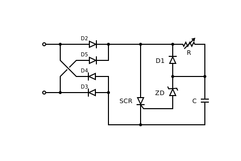
В первый момент времени тиристор SCR закрыт, а конденсатор C заряжается через резистор R. Напряжение входной полуволны продолжает нарастать, и в некоторый момент открывается динистор ZD, а за ним и тиристор SCR. Между клеммами начинает проходить значительный ток, пока напряжение полуволны не снизится до закрытия ZD. Конденсатор С при этом разрядится через диод D1 и тиристор SCR. Тиристор закроется. На следующем цикле процесс повторяется заново.
Нагрузка подключается последовательно (на рисунке клеммы слева).
Принцип действия такого диммера состоит в том, что открывая тиристор в разные моменты времени относительно перехода напряжения через 0, можно «обрезать» синусоидальные волны регулируемого напряжения и тем самым изменять действующее значение напряжения и ток в нагрузке.
Дроссель
Большинство диммеров используют ключевые схемы, производящие большое количество помех в широком диапазоне спектра. Эти помехи излучаются устройствами в эфир в виде электромагнитного излучения и поступают в провода, соединяющие диммер с источником питания и с регулируемой нагрузкой. Конструкции преобразователей питания часто содержат дроссели (индуктивности) в качестве реактивного элемента, а также LC фильтры как со стороны питания, так и со стороны нагрузки. С увеличением частоты преобразования, размеры дросселей становятся небольшими, а сочетание с хорошими фильтровыми конденсаторами с низким активным сопротивлением позволяет достичь приемлемого уровня помех. Современные диммеры уже не мешают работе радиоприемников.
Недостатки
Некоторые компании, в том числе мировые лидеры по производству электроустановочных изделий Schneider Electric и Тесо, уже производят диммеры для люминесцентных ламп, однако работоспособность его напрямую зависит от схемотехники электронно-пускорегулирующего аппарата (ЭПРА).
Источник
Что такое диммер, устройство и принцип работы

Д иммер — устройство для регулирования мощности и изменения яркости света от ламп накаливания / светодиодов. Термин произошел от английского «dim», что в переводе на русский означает «затемнять».
По сути, это упрощенная версия автотрансформатора (реостата) с меньшими размерами и весом.
Ниже рассмотрим, в чем особенности устройства, в каких сферах оно применяется, какими бывают электронные диммеры.
Отдельно разберем устройство и принцип работы, поговорим о видах, плюсах и минусах, а также особенностях эксплуатации.
Выделим несколько примеров и дадим подробные рекомендации по выбору.
Реостат как простейший диммер
Простыми словами, диммер — это реостат переменного тока, но с более сложной конструкцией. Впервые переменный резистор был изобретен Й. Поггендорфом в XIX веке для изменения напряжения (U, В) и тока (I, А) путем увеличения / уменьшения сопротивления (R, Ом).

В зависимости от типа реостата величина R меняется плавно или ступенчато.
Для снижения яркости источника света нужно уменьшить напряжение с помощью реостата, а для этого добавляется сопротивление.
Из-за увеличения R и I устройство сильно нагревается и отдает тепло в окружающий воздух. В результате такой регулятор имеет низкий КПД и, как следствие, не используется.
Применение
Благодаря простоте конструкции и функциональности, современные диммеры получили широкое распространение.

Светорегулятор оборудованы микроконтроллером и имеет широкий набор опций:
Электронные диммеры
Для тех, кто хочет углубится в тему.
Это небольшие по размеру и экономичные устройства, в основе работы которых лежит управляющий ключ: транзисторный или симисторный.
У большей части таких диммеров на выходе несинусоидальный сигнал, а секции синусоиды, «отрезаны» имеющимся ключом.

Такие диммеры не предназначены для подключения девайсов, питающихся от токов с низким коэффициентом гармоник.
К категории таких устройств относятся электрические двигатели, трансформаторы индукционного типа для галогенок и т. д. Это обусловлено риском поломки устройства из-за перегрева.
Кроме того, бюджетные электронные диммеры без специальных фильтров являются источниками сильных помех.
Устройство и принцип работы
Внешне диммеры напоминают обычные выключатели, но позволяют регулировать уровень яркости. Рассмотрим разные схемы исполнения и их особенности.

На тиристоре
В большинстве случае в качестве основного элемента применяется тиристор.

Общий алгоритм работы имеет следующий вид:


Благодаря открытию тиристора в определенный промежутки времени при переходе через «0», удается «обрезать» синусоиду и тем самым поменять параметр напряжения и нагрузочный ток.

С дросселем
Во многих диммерах применяются ключи, при добавлении которых в схему появляются электромагнитные (ЭМ) колебания в большом частотном диапазоне.

Такие волны приводят к появлению тока в проводах, объединяющих диммер, источник питания и нагрузку, тем самым создавая помехи.
Для борьбы с проблемой применяются дроссели индуктивности или LC-фильтры. Они устанавливаются около нагрузки или питающего источника.
Чем выше частота, тем компактней дроссель. При правильном выборе фильтра можно свести уровень помех к минимуму.
На резисторе
Диммеры на сопротивлении R применяются для изменения яркости ламп накаливания.
Конструктивно устройство состоит из реостата / переменного сопротивления, а работает на базе закона Ома.

При повышении сопротивления снижается ток в лампочке, что уменьшает активность нити накала.
Конструкция очень проста, но она имеет большой минус — неизменную потребляемую мощность вне зависимости от позиции регулировки.
Так, при повышении сопротивления снижается ток, но общая нагрузка остается неизменной. Лишняя энергия преобразуется в тепло и уходит в воздух.
Следовательно, сэкономить электричество с помощью таких устройств не получится.
Резисторные светорегуляторы редко, но применяются для изменения яркости ламп-полупроводников.
Речь идет об аналоговом способе управления, который почти не применяется из-за низкой экономичности и высокой чувствительности.
На симисторе
Такая схема немного сложней, чем резисторный вариант. Здесь применяется симистор, играющий роль ключа и меняющий параметры тока.

В процессе работы напряжение представляет собой куски отрицательных / положительных полуволн, а при уменьшении яркости лампочка питается «обрубками».


На ШИМ-генератор приходит 200-герцовый сигнал. При этом яркость меняется с учетом временного промежутка и длины импульса. Параметры тока / частоты при этом остаются неизменными.
Несмотря на большую сложность исполнения, схема на симисторах имеет ряд плюсов.

Виды устройств
В зависимости от сферы применения и задач, которые возлагаются на диммер, он может отличаться по внешнему виду, стоимости и функционалу.
Ниже рассмотрим основные типы диммеров, которые отличаются по монтажу, управлению и виду ламп.
По способу установки
По особенностям монтажа все диммеры можно разделить на несколько типов:
По управлению
Все диммеры отличаются по способу управления:
По типу передачи сигнала
В большинстве современных диммеров предусмотрена возможность дистанционного управления.
Здесь возможны следующие варианты:
По виду применяемых ламп
Для каждого типа ламп используется совместимая модель диммера. Если завод-изготовитель заявляет о поддержке нескольких видов источников света, внутри оборудования смонтирован «умный» регулятор, а это сказывается на стоимости.
Здесь выделяется два вида устройств:
Преимущества и недостатки
При рассмотрении диммеров необходимо понимать их слабые и сильные стороны.
Особенности установки
Установка диммера в доме или квартире не вызывает проблем. Благодаря простой конструкции, светорегулятор легко монтируется вместо обычных выключателей и подключается по аналогичной схеме.

При покупке полупроводниковых приборов обратите внимание на совместимость. При наличие таковой на коробке должна быть надпись «dimmable».

Также необходимо смотреть способ монтажа, ведь некоторые модели имеют накладную конструкцию или встраиваются в разрыв питающих проводов. Подробнее об этом мы говорили выше.
Особенности эксплуатации
При покупке и использовании диммеров важно учесть ряд особенностей их применения.
Выделим базовые нюансы:
Пример популярных моделей и их характеристики
Современный рынок радует покупателей огромным количеством диммеров, отличающихся конструктивными особенностями, способом крепления, производителем и другими параметрами.
Ниже выделим несколько наиболее востребованных вариантов.
Диммер сенсорный RF6-18, 12/24 В, 3*6А/18A, 216/432 Вт, IP20
Светорегулятор с сенсорным управлением, предназначенный для подсветки светодиодных ламп на 12 и 24 Вольта. Управление осуществляется с помощью пульта ДУ.

Возможности диммера позволяют включать / выключать ленту и менять яркость.
Диммер EKF Минск ERD06-101-10
Светорегулятор в рамке, предназначенный для вертикально / горизонтальной скрытой установки.

Работает с лампами накаливания и галогенками на напряжение до 230 В. Крепится в распор или с помощью шурупов. Поставляется в комплекте с рамкой.
Включение осуществляется путем поворота или посредством поворота с нажимом.
Диммер-мини WI-FI 12-24 В, 8A, 96/192 Вт, IP20
Небольшой светорегулятор, предназначенный для управления 12-ти или 24-вольтной светодиодной ленты с телефонов на Андроид или iOS. Работает по радиоканалу.

С его помощью можно включать / отключать устройство, поменять яркость. Диммер можно программировать.
Рекомендации по выбору
При покупке диммеров для светодиодных ламп, в том числе работающих в магнитоле / светильнике, нужно с умом подойти к выбору. При поиске подходящего варианта обратите внимание на следующие моменты.
Тип ламп
Светорегуляторы способны работать с определенными видами лампочек, ведь универсальных устройств не существует.
Диммеры могут поддерживать лампы накаливания, галогенки, светодиодные устройства, LED-модули и другие источники света.
Рассмотрим тонкости выбора для разных видов ламп:

Мощность
При выборе диммера по мощности необходимо подсчитать суммарную нагрузку. Если неправильно сделать вычисления, устройство может не заработать или выйдет из строя раньше срока.
Для расчета суммарной мощности лампочек сложите параметры, которые указаны на упаковке.
При выборе светорегулятора обязательно добавляйте 20-50% к расчетной мощности. К примеру, если полученный параметр 200 Вт, лучше брать диммер на 300 Вт.
Особенности исполнения
При выборе обратите внимание на тип диммера, ведь от этого зависит возможность его монтажа и сочетание с дизайном помещения.
Как отмечалось, на рынке можно найти клавишные, поворотно-нажимные, сенсорные и другие модели.

Дополнительные советы
При покупке диммера в магазине обязательно проверьте его на исправность и возможность применения с указанным типом лампы.
Убедитесь, что все функции (в том числе запоминания уровня освещения), работают.
Также при выборе обратите внимание на производителя, срок службы, цвет и особенности управления.
Проверьте комплектацию на факт наличия всех элементов для монтажа и инструкции на русском языке.
Диммеры — востребованные устройства, которые давно применяются для регулирования света в лампах накаливания и набирают популярности в других направлениях.
Сегодня с их помощью можно регулировать яркость света в магнитоле, в светильнике или лампочках разного типа на 12, 24 или 220 В.
Источник
Теперь вы знаете какие однокоренные слова подходят к слову Диммер как правильно пишется, а так же какой у него корень, приставка, суффикс и окончание. Вы можете дополнить список однокоренных слов к слову «Диммер как правильно пишется», предложив свой вариант в комментариях ниже, а также выразить свое несогласие проведенным с морфемным разбором.
ДИММЕР
- ДИММЕР
-
- ДИММЕР
-
[англ. dimmer — реостат] — техн. бесступенчатый переключатель, регулятор света в помещениях. Нем. Dimmer.
Словарь иностранных слов.- Комлев Н.Г.,
2006.
.
Синонимы:
Смотреть что такое «ДИММЕР» в других словарях:
-
диммер — сущ., кол во синонимов: 1 • регулятор (27) Словарь синонимов ASIS. В.Н. Тришин. 2013 … Словарь синонимов
-
Диммер — Ц устройство для плавного регулирования силы света лампы. Источник: Словарь архитектурно строительных терминов … Строительный словарь
-
Диммер — – устройство для плавного регулирования силы света лампы … Словарь строителя
-
Диммер — Современный многофункциональный выключатель. Диммер (от англ. dim затемнять, в русском языке светорегулятор, во французском вариатор) … Википедия
-
Светорегулятор — Диммер (от англ. dim затемнять) регулятор электрической мощности нагрузки, включаемый последовательно с ней. Обычно используется для регулировки яркости свечения ламп накаливания. В простейшем случае может представлять собой переменный резистор … Википедия
-
Мардук — У этого термина существуют и другие значения, см. Мардук (значения). Древняя Месопотамия Ассириология Области и государства Город … Википедия
-
Меродах — Междуречье Евфрат · Тигр Ассириология Города / Государства Шумер: Урук · Ур · Эриду · Киш · Лагаш · Умма · Ниппур … Википедия
-
Триммер — В Викисловаре есть статья «триммер» Триммер: Триммер электрическая машинка для стрижки волос. Триммер переносная газ … Википедия
-
Сборная Люксембурга по футболу — Прозвища D Roud Léiwen (Красные львы) … Википедия
-
Тиристорный регулятор мощности — Эту статью следует викифицировать. Пожалуйста, оформите её согласно правилам оформления статей … Википедия