In electromagnetism and electronics, electromotive force (also electromotance, abbreviated emf,[1][2] denoted  or
or  ) is an energy transfer to an electric circuit per unit of electric charge, measured in volts. Devices called electrical transducers provide an emf[3] by converting other forms of energy into electrical energy.[3] Other electrical equipment also produce an emf, such as batteries, which convert chemical energy, and generators, which convert mechanical energy.[4] This energy conversion is achieved by physical forces applying physical work on electric charges. However, electromotive force itself is not a physical force,[5] and ISO/IEC standards have deprecated the term in favor of source voltage or source tension instead (denoted
  ).[6][7]
An electronic–hydraulic analogy may view emf as the mechanical work done to water by a pump, which results in a pressure difference (analogous to voltage).[8]
In electromagnetic induction, emf can be defined around a closed loop of a conductor as the electromagnetic work that would be done on an elementary electric charge (such as an electron) if it travels once around the loop.[9]
For two-terminal devices modeled as a Thévenin equivalent circuit, an equivalent emf can be measured as the open-circuit voltage between the two terminals. This emf can drive an electric current if an external circuit is attached to the terminals, in which case the device becomes the voltage source of that circuit.
Although an emf gives rise to a voltage and can be measured as a voltage and may sometimes informally be called a «voltage», they are not the same phenomenon (see § Distinction with potential difference).
Overview[edit]
Devices that can provide emf include electrochemical cells, thermoelectric devices, solar cells, photodiodes, electrical generators, inductors, transformers and even Van de Graaff generators.[10][11] In nature, emf is generated when magnetic field fluctuations occur through a surface. For example, the shifting of the Earth’s magnetic field during a geomagnetic storm induces currents in an electrical grid as the lines of the magnetic field are shifted about and cut across the conductors.
In a battery, the charge separation that gives rise to a potential difference (voltage) between the terminals is accomplished by chemical reactions at the electrodes that convert chemical potential energy into electromagnetic potential energy.[12][13] A voltaic cell can be thought of as having a «charge pump» of atomic dimensions at each electrode, that is:
A (chemical) source of emf can be thought of as a kind of charge pump that acts to move positive charges from a point of low potential through its interior to a point of high potential. … By chemical, mechanical or other means, the source of emf performs work
on that charge to move it to the high-potential terminal. The emf


In an electrical generator, a time-varying magnetic field inside the generator creates an electric field via electromagnetic induction, which creates a potential difference between the generator terminals. Charge separation takes place within the generator because electrons flow away from one terminal toward the other, until, in the open-circuit case, an electric field is developed that makes further charge separation impossible. The emf is countered by the electrical voltage due to charge separation. If a load is attached, this voltage can drive a current. The general principle governing the emf in such electrical machines is Faraday’s law of induction.
History[edit]
In 1801, Alessandro Volta introduced the term «force motrice électrique» to describe the active agent of a battery (which he had invented around 1798).[15]
This is called the «electromotive force» in English.
Around 1830, Michael Faraday established that chemical reactions at each of two electrode–electrolyte interfaces provide the «seat of emf» for the voltaic cell. That is, these reactions drive the current and are not an endless source of energy as the earlier obsolete theory thought.[16] In the open-circuit case, charge separation continues until the electrical field from the separated charges is sufficient to arrest the reactions. Years earlier, Alessandro Volta, who had measured a contact potential difference at the metal–metal (electrode–electrode) interface of his cells, held the incorrect opinion that contact alone (without taking into account a chemical reaction) was the origin of the emf.
Notation and units of measurement[edit]
Electromotive force is often denoted by or ℰ.
In a device without internal resistance, if an electric charge  passing through that device gains an energy
  via work, the net emf for that device is the energy gained per unit charge:
  Like other measures of energy per charge, emf uses the SI unit volt, which is equivalent to a joule (SI unit of energy) per coulomb (SI unit of charge).[17]
Electromotive force in electrostatic units is the statvolt (in the centimeter gram second system of units equal in amount to an erg per electrostatic unit of charge).
Formal definitions[edit]
Inside a source of emf (such as a battery) that is open-circuited, a charge separation occurs between the negative terminal N and the positive terminal P.
This leads to an electrostatic field  that points from P to N, whereas the emf of the source must be able to drive current from N to P when connected to a circuit.
This led Max Abraham[18] to introduce the concept of a nonelectrostatic field  that exists only inside the source of emf.
In the open-circuit case,  , while when the source is connected to a circuit the electric field
  inside the source changes but remains essentially the same.
In the open-circuit case, the conservative electrostatic field created by separation of charge exactly cancels the forces producing the emf.[19]
Mathematically:

where is the conservative electrostatic field created by the charge separation associated with the emf,  is an element of the path from terminal N to terminal P, ‘
 ‘ denotes the vector dot product, and
  is the electric scalar potential.[20]
This emf is the work done on a unit charge by the source’s nonelectrostatic field when the charge moves from N to P.
When the source is connected to a load, its emf is just

and no longer has a simple relation to the electric field inside it.
In the case of a closed path in the presence of a varying magnetic field, the integral of the electric field around the (stationary) closed loop  may be nonzero.
Then, the «induced emf» (often called the «induced voltage») in the loop is:[21]

where is the entire electric field, conservative and non-conservative, and the integral is around an arbitrary, but stationary, closed curve through which there is a time-varying magnetic flux  , and
, and  is the vector potential.
The electrostatic field does not contribute to the net emf around a circuit because the electrostatic portion of the electric field is conservative (i.e., the work done against the field around a closed path is zero, see Kirchhoff’s voltage law, which is valid, as long as the circuit elements remain at rest and radiation is ignored[22]).
That is, the «induced emf» (like the emf of a battery connected to a load) is not a «voltage» in the sense of a difference in the electric scalar potential.
If the loop is a conductor that carries current  in the direction of integration around the loop, and the magnetic flux is due to that current, we have that
  , where
  is the self inductance of the loop.
If in addition, the loop includes a coil that extends from point 1 to 2, such that the magnetic flux is largely localized to that region, it is customary to speak of that region as an inductor, and to consider that its emf is localized to that region.
Then, we can consider a different loop  that consists of the coiled conductor from 1 to 2, and an imaginary line down the center of the coil from 2 back to 1.
The magnetic flux, and emf, in loop is essentially the same as that in loop :

For a good conductor,  is negligible, so we have, to a good approximation,

where is the electric scalar potential along the centerline between points 1 and 2.
Thus, we can associate an effective «voltage drop»  with an inductor (even though our basic understanding of induced emf is based on the vector potential rather than the scalar potential), and consider it as a load element in Kirchhoff’s voltage law,

where now the induced emf is not considered to be a source emf.[23]
This definition can be extended to arbitrary sources of emf and paths moving with velocity  through the electric field and magnetic field
  :[24]
:[24]
![{displaystyle {begin{aligned}{mathcal {E}}&=oint _{C}left[{boldsymbol {E}}+{boldsymbol {v}}times {boldsymbol {B}}right]cdot mathrm {d} {boldsymbol {ell }}\&qquad +{frac {1}{q}}oint _{C}mathrm {Effective chemical forces cdot } mathrm {d} {boldsymbol {ell }}\&qquad qquad +{frac {1}{q}}oint _{C}mathrm {Effective thermal forces cdot } mathrm {d} {boldsymbol {ell }} ,end{aligned}}}](https://wikimedia.org/api/rest_v1/media/math/render/svg/4d30a15eac236d54cf1c56bd3b8cbb91fd8d9fb3)
which is a conceptual equation mainly, because the determination of the «effective forces» is difficult.
The term ![{displaystyle oint _{C}left[{boldsymbol {E}}+{boldsymbol {v}}times {boldsymbol {B}}right]cdot mathrm {d} {boldsymbol {ell }}}](https://wikimedia.org/api/rest_v1/media/math/render/svg/a92bcd9e5016deec860a048a08132ca5c97f65d0)
is often called a «motional emf».
In (electrochemical) thermodynamics[edit]
When multiplied by an amount of charge  the emf yields a thermodynamic work term
  that is used in the formalism for the change in Gibbs energy when charge is passed in a battery:

where  is the Gibbs free energy,
  is the entropy, is the system volume,
  is its pressure and
  is its absolute temperature.
The combination  is an example of a conjugate pair of variables. At constant pressure the above relationship produces a Maxwell relation that links the change in open cell voltage with temperature (a measurable quantity) to the change in entropy when charge is passed isothermally and isobarically. The latter is closely related to the reaction entropy of the electrochemical reaction that lends the battery its power. This Maxwell relation is:[25]

If a mole of ions goes into solution (for example, in a Daniell cell, as discussed below) the charge through the external circuit is:

where  is the number of electrons/ion, and
  is the Faraday constant and the minus sign indicates discharge of the cell. Assuming constant pressure and volume, the thermodynamic properties of the cell are related strictly to the behavior of its emf by:[25]

where  is the enthalpy of reaction. The quantities on the right are all directly measurable. Assuming constant temperature and pressure:

which is used in the derivation of the Nernst equation.
Distinction with potential difference[edit]
Although an electrical potential difference (voltage) is sometimes called an emf,[26][27][28][29][30] however they are formally distinct concepts:
- Emf is the cause of a potential difference. Potential difference in turn is a cause of current flow.
- Potential difference itself is not the cause of an emf.
- Consider Kirchhoff’s voltage law, which says the sum of potential differences going through any loop in a circuit is zero. For a circuit of a voltage source and a resistor, the sum of the source’s applied voltage plus the ohmic voltage drop through the resistor is zero. But the resistor provides no emf, only the voltage source does:
- For a circuit using a battery source, the emf is due solely to the chemistry in the battery that causes charge separation, which generates a potential difference.
- For a circuit using an electric generator, the emf is due solely to a time-varying magnetic field within the generator that causes charge separation, which generates a potential difference.
- Consider Kirchhoff’s voltage law, which says the sum of potential differences going through any loop in a circuit is zero. For a circuit of a voltage source and a resistor, the sum of the source’s applied voltage plus the ohmic voltage drop through the resistor is zero. But the resistor provides no emf, only the voltage source does:
- Both a 1 volt emf and a 1 volt potential difference correspond to 1 joule per coulomb of charge. However:
- a 1 volt emf means that the source supplies an energy of 1 joule to each coulomb of charge passing through.
- a 1 volt potential difference between two points on a circuit means that each coulomb of charge will need to either:
- gain 1 joule of energy to move up that potential difference,
- or give up 1 joule of energy to move down that potential difference.[31]
In the case of an open circuit, the electric charge that has been separated by the mechanism generating the emf creates an electric field opposing the separation mechanism. For example, the chemical reaction in a voltaic cell stops when the opposing electric field at each electrode is strong enough to arrest the reactions. A larger opposing field can reverse the reactions in what are called reversible cells.[32][33]
The electric charge that has been separated creates an electric potential difference that can (in many cases) be measured with a voltmeter between the terminals of the device, when not connected to a load. The magnitude of the emf for the battery (or other source) is the value of this open-circuit voltage.
When the battery is charging or discharging, the emf itself cannot be measured directly using the external voltage because some voltage is lost inside the source.[27]
It can, however, be inferred from a measurement of the current and potential difference , provided that the internal resistance  already has been measured:
«Potential difference» is not the same as «induced emf» (often called «induced voltage»).
The potential difference (difference in the electric scalar potential) between two points A and B is independent of the path we take from A to B.
If a voltmeter always measured the potential difference between A and B, then the position of the voltmeter would make no difference.
However, it is quite possible for the measurement by a voltmeter between points A and B to depend on the position of the voltmeter, if a time-dependent magnetic field is present.
For example, consider an infinitely long solenoid using an AC current to generate a varying flux in the interior of the solenoid.
Outside the solenoid we have two resistors connected in a ring around the solenoid.
The resistor on the left is 100 Ω and the one on the right is 200 Ω, they are connected at the top and bottom at points A and B.
The induced voltage, by Faraday’s law is , so the current  Therefore the voltage across the 100 Ω resistor is
  and the voltage across the 200 Ω resistor is
  , yet the two resistors are connected on both ends, but
  measured with the voltmeter to the left of the solenoid is not the same as measured with the voltmeter to the right of the solenoid.[34]
[35]
Generation[edit]
Chemical sources[edit]

A typical reaction path requires the initial reactants to cross an energy barrier, enter an intermediate state and finally emerge in a lower energy configuration. If charge separation is involved, this energy difference can result in an emf. See Bergmann et al.[36] and Transition state.

The question of how batteries (galvanic cells) generate an emf occupied scientists for most of the 19th century. The «seat of the electromotive force» was eventually determined in 1889 by Walther Nernst[37] to be primarily at the interfaces between the electrodes and the electrolyte.[16]
Atoms in molecules or solids are held together by chemical bonding, which stabilizes the molecule or solid (i.e. reduces its energy). When molecules or solids of relatively high energy are brought together, a spontaneous chemical reaction can occur that rearranges the bonding and reduces the (free) energy of the system.[38] In batteries, coupled half-reactions, often involving metals and their ions, occur in tandem, with a gain of electrons (termed «reduction») by one conductive electrode and loss of electrons (termed «oxidation») by another (reduction-oxidation or redox reactions). The spontaneous overall reaction can only occur if electrons move through an external wire between the electrodes. The electrical energy given off is the free energy lost by the chemical reaction system.
As an example, a Daniell cell consists of a zinc anode (an electron collector) that is oxidized as it dissolves into a zinc sulfate solution. The dissolving zinc leaving behind its electrons in the electrode according to the oxidation reaction (s = solid electrode; aq = aqueous solution):

The zinc sulfate is the electrolyte in that half cell. It is a solution which contains zinc cations  , and sulfate anions
  with charges that balance to zero.
In the other half cell, the copper cations in a copper sulfate electrolyte move to the copper cathode to which they attach themselves as they adopt electrons from the copper electrode by the reduction reaction:

which leaves a deficit of electrons on the copper cathode. The difference of excess electrons on the anode and deficit of electrons on the cathode creates an electrical potential between the two electrodes. (A detailed discussion of the microscopic process of electron transfer between an electrode and the ions in an electrolyte may be found in Conway.)[39] The electrical energy released by this reaction (213 kJ per 65.4 g of zinc) can be attributed mostly due to the 207 kJ weaker bonding (smaller magnitude of the cohesive energy) of zinc, which has filled 3d- and 4s-orbitals, compared to copper, which has an unfilled orbital available for bonding.
If the cathode and anode are connected by an external conductor, electrons pass through that external circuit (light bulb in figure), while ions pass through the salt bridge to maintain charge balance until the anode and cathode reach electrical equilibrium of zero volts as chemical equilibrium is reached in the cell. In the process the zinc anode is dissolved while the copper electrode is plated with copper.[40] The salt bridge has to close the electrical circuit while preventing the copper ions from moving to the zinc electrode and being reduced there without generating an external current. It is not made of salt but of material able to wick cations and anions (a dissociated salt) into the solutions. The flow of positively charged cations along the bridge is equivalent to the same number of negative charges flowing in the opposite direction.
If the light bulb is removed (open circuit) the emf between the electrodes is opposed by the electric field due to the charge separation, and the reactions stop.
For this particular cell chemistry, at 298 K (room temperature), the emf = 1.0934 V, with a temperature coefficient of  = −4.53×10⁻⁴ V/K.[25]
Voltaic cells[edit]
Volta developed the voltaic cell about 1792, and presented his work March 20, 1800.[41] Volta correctly identified the role of dissimilar electrodes in producing the voltage, but incorrectly dismissed any role for the electrolyte.[42] Volta ordered the metals in a ‘tension series’, «that is to say in an order such that any one in the list becomes positive when in contact with any one that succeeds, but negative by contact with any one that precedes it.»[43] A typical symbolic convention in a schematic of this circuit ( –||– ) would have a long electrode 1 and a short electrode 2, to indicate that electrode 1 dominates. Volta’s law about opposing electrode emfs implies that, given ten electrodes (for example, zinc and nine other materials), 45 unique combinations of voltaic cells (10 × 9/2) can be created.
Typical values[edit]
The electromotive force produced by primary (single-use) and secondary (rechargeable) cells is usually of the order of a few volts. The figures quoted below are nominal, because emf varies according to the size of the load and the state of exhaustion of the cell.
| EMF | Cell chemistry | Common name | ||
|---|---|---|---|---|
| Anode | Solvent, electrolyte | Cathode | ||
| 1.2 V | Cadmium | Water, potassium hydroxide | NiO(OH) | nickel-cadmium |
| 1.2 V | Mischmetal (hydrogen absorbing) | Water, potassium hydroxide | Nickel | nickel–metal hydride |
| 1.5 V | Zinc | Water, ammonium or zinc chloride | Carbon, manganese dioxide | Zinc carbon |
| 2.1 V | Lead | Water, sulfuric acid | Lead dioxide | Lead–acid |
| 3.6 V to 3.7 V | Graphite | Organic solvent, Li salts | LiCoO2 | Lithium-ion |
| 1.35 V | Zinc | Water, sodium or potassium hydroxide | HgO | Mercury cell |
Other chemical sources[edit]
Other chemical sources include fuel cells.
Electromagnetic induction[edit]
Electromagnetic induction is the production of a circulating electric field by a time-dependent magnetic field. A time-dependent magnetic field can be produced either by motion of a magnet relative to a circuit, by motion of a circuit relative to another circuit (at least one of these must be carrying an electric current), or by changing the electric current in a fixed circuit. The effect on the circuit itself, of changing the electric current, is known as self-induction; the effect on another circuit is known as mutual induction.
For a given circuit, the electromagnetically induced emf is determined purely by the rate of change of the magnetic flux through the circuit according to Faraday’s law of induction.
An emf is induced in a coil or conductor whenever there is change in the flux linkages. Depending on the way in which the changes are brought about, there are two types: When the conductor is moved in a stationary magnetic field to procure a change in the flux linkage, the emf is statically induced. The electromotive force generated by motion is often referred to as motional emf. When the change in flux linkage arises from a change in the magnetic field around the stationary conductor, the emf is dynamically induced. The electromotive force generated by a time-varying magnetic field is often referred to as transformer emf.
Contact potentials[edit]
When solids of two different materials are in contact, thermodynamic equilibrium requires that one of the solids assume a higher electrical potential than the other. This is called the contact potential.[44] Dissimilar metals in contact produce what is known also as a contact electromotive force or Galvani potential. The magnitude of this potential difference is often expressed as a difference in Fermi levels in the two solids when they are at charge neutrality, where the Fermi level (a name for the chemical potential of an electron system[45][46]) describes the energy necessary to remove an electron from the body to some common point (such as ground).[47] If there is an energy advantage in taking an electron from one body to the other, such a transfer will occur. The transfer causes a charge separation, with one body gaining electrons and the other losing electrons. This charge transfer causes a potential difference between the bodies, which partly cancels the potential originating from the contact, and eventually equilibrium is reached. At thermodynamic equilibrium, the Fermi levels are equal (the electron removal energy is identical) and there is now a built-in electrostatic potential between the bodies.
The original difference in Fermi levels, before contact, is referred to as the emf.[48]
The contact potential cannot drive steady current through a load attached to its terminals because that current would involve a charge transfer. No mechanism exists to continue such transfer and, hence, maintain a current, once equilibrium is attained.
One might inquire why the contact potential does not appear in Kirchhoff’s law of voltages as one contribution to the sum of potential drops. The customary answer is that any circuit involves not only a particular diode or junction, but also all the contact potentials due to wiring and so forth around the entire circuit. The sum of all the contact potentials is zero, and so they may be ignored in Kirchhoff’s law.[49][50]
Solar cell[edit]

Operation of a solar cell can be understood from its equivalent circuit. Photons with energy greater than the bandgap of the semiconductor create mobile electron–hole pairs. Charge separation occurs because of a pre-existing electric field associated with the p-n junction. This electric field is created from a built-in potential, which arises from the contact potential between the two different materials in the junction. The charge separation between positive holes and negative electrons across the p–n diode yields a forward voltage, the photo voltage, between the illuminated diode terminals,[51] which drives current through any attached load. Photo voltage is sometimes referred to as the photo emf, distinguishing between the effect and the cause.
Solar cell current–voltage relationship[edit]
Two internal current losses  limit the total current available to the external circuit. The light-induced charge separation eventually creates a forward current
  through the cell’s internal resistance
  in the direction opposite the light-induced current
  . In addition, the induced voltage tends to forward bias the junction, which at high enough voltages will cause a recombination current
  in the diode opposite the light-induced current.
When the output is short-circuited, the output voltage is zeroed, and so the voltage across the diode is smallest. Thus, short-circuiting results in the smallest losses and consequently the maximum output current, which for a high-quality solar cell is approximately equal to the light-induced current .[52] Approximately this same current is obtained for forward voltages up to the point where the diode conduction becomes significant.
The current delivered by the illuminated diode to the external circuit can be simplified (based on certain assumptions) to:

 is the reverse saturation current. Two parameters that depend on the solar cell construction and to some degree upon the voltage itself are the ideality factor m and the thermal voltage
  , which is about 26 millivolts at room temperature.[52]
Solar cell photo emf[edit]

Solar cell output voltage for two light-induced currents IL expressed as a ratio to the reverse saturation current I0[53] and using a fixed ideality factor m of 2.[54] Their emf is the voltage at their y-axis intercept.
Solving the illuminated diode’s above simplified current–voltage relationship for output voltage yields:

which is plotted against  in the figure.
The solar cell’s photo emf  has the same value as the open-circuit voltage
  , which is determined by zeroing the output current :

It has a logarithmic dependence on the light-induced current and is where the junction’s forward bias voltage is just enough that the forward current completely balances the light-induced current. For silicon junctions, it is typically not much more than 0.5 volts.[55] While for high-quality silicon panels it can exceed 0.7 volts in direct sunlight.[56]
When driving a resistive load, the output voltage can be determined using Ohm’s law and will lie between the short-circuit value of zero volts and the open-circuit voltage .[57] When that resistance is small enough such that  (the near-vertical part of the two illustrated curves), the solar cell acts more like a current generator rather than a voltage generator,[58] since the current drawn is nearly fixed over a range of output voltages. This contrasts with batteries, which act more like voltage generators.
Other sources that generate emf[edit]
- A transformer coupling two circuits may be considered a source of emf for one of the circuits, just as if it were caused by an electrical generator; this is the origin of the term «transformer emf».
- For converting sound waves into voltage signals:
- a microphone generates an emf from a moving diaphragm.
- a magnetic pickup generates an emf from a varying magnetic field produced by an instrument.
- a piezoelectric sensor generates an emf from strain on a piezoelectric crystal.
- Devices that use temperature to produce emfs include thermocouples and thermopiles.[59]
- Any electrical transducer which converts a physical energy into electrical energy.
See also[edit]
- Counter-electromotive force
- Electric battery
- Electrochemical cell
- Electrolytic cell
- Galvanic cell
- Voltaic pile
References[edit]
- ^ «EMF». American Heritage Dictionary of the English Language, 3rd ed. Houghton Mifflin. 1992.
- ^ «EMF». Oxford English Dictionary.
- ^ a b Tipler, Paul A. (January 1976). Physics. New York, NY: Worth Publishers, Inc. p. 803. ISBN 978-0-87901-041-6.
- ^ Stewart, Joseph V. (2001). Intermediate electromagnetic theory. Singapore River Edge, NJ: World Scientific. p. 389. ISBN 978-981-02-4470-5. OCLC 47127179.
- ^ Matthews, Michael R. (2014-07-03). International Handbook of Research in History, Philosophy and Science Teaching. Springer. p. 142. ISBN 978-94-007-7654-8.
[Volta] stated that a new type of «force» was acting upon the charges, separating them and keeping them separated, and he called this action the electromotive force, the name that is still applied.
- ^ «IEC 60050 — International Electrotechnical Vocabulary — Details for IEV number 131-12-22: «source voltage»«. www.electropedia.org. Retrieved 2022-12-19.
- ^ «IEC 80000-6:2022». International Organization for Standardization. Retrieved 2022-12-19.
- ^ Langmuir, Irving (1916). «The Relation Between Contact Potentials and Electrochemical Action». Transactions of the American Electrochemical Society. The Society. 29: 175.
- ^ Cook, David M. (2003). The Theory of the Electromagnetic Field. Courier Dover. p. 157. ISBN 978-0-486-42567-2.
- ^ Lerner, Lawrence M. (1997). Physics for scientists and engineers. Jones & Bartlett Publishers. pp. 724–727. ISBN 978-0-7637-0460-5.
- ^ Tipler, Paul A.; Mosca, Gene (2007). Physics for Scientists and Engineers (6 ed.). Macmillan. p. 850. ISBN 978-1-4292-0124-7.
- ^ Halpern, Alvin M.; Erlbach, Erich (1998). Schaum’s outline of theory and problems of beginning physics II. McGraw-Hill Professional. p. 138. ISBN 978-0-07-025707-8.
- ^ Lehrman, Robert L. (1998). Physics the easy way. Barron’s Educational Series. p. 274. ISBN 978-0-7641-0236-3.
emf separated charge reaction potential.
- ^ Singh, Kongbam Chandramani (2009). «§3.16 EMF of a source». Basic Physics. Prentice Hall India. p. 152. ISBN 978-81-203-3708-4.
- ^
Volta, Alessandro (1801). «De l’électricité dite galvanique». Annales de Chimie. Chez Fuchs, Paris. - ^ a b Cajori, Florian (1899). A History of Physics in Its Elementary Branches: Including the Evolution of Physical Laboratories. The Macmillan Company. pp. 218–219.
seat of electromotive force.
- ^
Valkenburgh, Van (1995). Basic Electricity. Cengage Learning. pp. 1–46. ISBN 978-0-7906-1041-2. - ^
Abraham, M.; Becker, R. (1932). The Classical Theory of Electricity and Magnetism. Blackie & Son. p. 116-122. - ^
Griffiths, David J (1999). Introduction to Electrodynamics (3rd ed.). Pearson/Addison-Wesley. p. 293. ISBN 978-0-13-805326-0. - ^
Only the electric field that results from charge separation caused by the emf is counted. While a solar cell has an electric field that results from a contact potential (see contact potentials and solar cells), this electric field component is not included in the integral. Only the electric field that results from charge separation caused by photon energy is included. - ^ Olenick, Richard P.; Apostol, Tom M.; Goodstein, David L. (1986). Beyond the mechanical universe: from electricity to modern physics. Cambridge University Press. p. 245. ISBN 978-0-521-30430-6.
- ^
McDonald, Kirk T. (2012). «Voltage Drop, Potential Difference and EMF» (PDF). Physics Examples. Princeton University. - ^ Feynman, R.P.; Leighton, R.B.; Sands, M. (1964). The Feynman Lectures on Physics, Vol. II, chap. 22. Addison Wesley.
- ^ Cook, David M. (2003). The Theory of the Electromagnetic Field. Courier Dover. p. 158. ISBN 978-0-486-42567-2.
- ^ a b c Finn, Colin B P (1992). Thermal Physics. CRC Press. p. 163. ISBN 978-0-7487-4379-7.
- ^
Fogiel, M. (2002). Basic Electricity. Research & Education Association. p. 76. ISBN 978-0-87891-420-3. - ^ a b
Halliday, David; Resnick, Robert; Walker, Jearl (2008). Fundamentals of Physics (6th ed.). Wiley. p. 638. ISBN 978-0-471-75801-3. - ^
Freeman, Roger L (2005). Fundamentals of Telecommunications (2nd ed.). Wiley. p. 576. ISBN 978-0-471-71045-5. - ^
Croft, Terrell (1917). Practical Electricity. McGraw-Hill. p. 533. - ^
Loeb, Leonard B. (2007). Fundamentals of Electricity and Magnetism (Reprint of Wiley 1947 3rd ed.). Read Books. p. 86. ISBN 978-1-4067-0733-5. - ^ «Difference Between Voltage and EMF?». Electrical Technology. 2019-10-06. Archived from the original on 2022-04-08. Retrieved 2022-09-28.
- ^
Warn, J. R. W.; Peters, A. P. H. (1996). Concise Chemical Thermodynamics (2 ed.). CRC Press. p. 123. ISBN 978-0-7487-4445-9. - ^
Glasstone, Samuel (2007). Thermodynamics for Chemists (Reprint of D. Van Nostrand Co (1964) ed.). Read Books. p. 301. ISBN 978-1-4067-7322-4. - ^ Shadowitz, Albert (1975). The Electromagnetic Field (1st ed.). McGraw-Hill Book Company. pp. 396–398. ISBN 0-07-056368-3.
- ^
McDonald, Kirk T. (2010). «Lewin’s Circuit Paradox» (PDF). Physics Examples. Princeton University. - ^ Risch, Nikolaus (2002). «Molecules — bonds and reactions». In L Bergmann; et al. (eds.). Constituents of Matter: Atoms, Molecules, Nuclei, and Particles. CRC Press. ISBN 978-0-8493-1202-1.
- ^ Nernst, Walter (1889). «Die elektromotorische Wirksamkeit der Ionen». Z. Phys. Chem. 4: 129.
- ^
The brave reader can find an extensive discussion for organic electrochemistry in Amatore, Christian (2000). «Basic concepts». In Henning Lund; Ole Hammerich (eds.). Organic electrochemistry (4 ed.). CRC Press. ISBN 978-0-8247-0430-8. - ^
Conway, BE (1999). «Energy factors in relation to electrode potential». Electrochemical supercapacitors. Springer. p. 37. ISBN 978-0-306-45736-4. - ^ Tilley, R. J. D. (2004). Understanding Solids. Wiley. p. 267. ISBN 978-0-470-85275-0.
- ^ Mottelay, Paul Fleury (2008). Bibliographical History of Electricity and Magnetism (Reprint of 1892 ed.). Read Books. p. 247. ISBN 978-1-4437-2844-7.
- ^ Kragh, Helge (2000). «Confusion and Controversy: Nineteenth-century theories of the voltaic pile» (PDF). Nuova Voltiana:Studies on Volta and His Times. Università degli studi di Pavia. Archived from the original (PDF) on 2009-03-20.
- ^ Cumming, Linnaus (2008). An Introduction to the Theory of Electricity (Reprint of 1885 ed.). BiblioBazaar. p. 118. ISBN 978-0-559-20742-6.
- ^ Trigg, George L. (1995). Landmark experiments in twentieth century physics (Reprint of Crane, Russak & Co 1975 ed.). Courier Dover. p. 138 ff. ISBN 978-0-486-28526-9.
- ^ Rockett, Angus (2007). «Diffusion and drift of carriers». Materials science of semiconductors. New York, NY: Springer Science. p. 74 ff. ISBN 978-0-387-25653-5.
- ^ Kittel, Charles (2004). «Chemical potential in external fields». Elementary Statistical Physics (Reprint of Wiley 1958 ed.). Courier Dover. p. 67. ISBN 978-0-486-43514-5.
- ^ Hanson, George W. (2007). Fundamentals of Nanoelectronics. Prentice Hall. p. 100. ISBN 978-0-13-195708-4.
- ^ Sato, Norio (1998). «Semiconductor photoelectrodes». Electrochemistry at metal and semiconductor electrodes (2nd ed.). Elsevier. p. 110 ff. ISBN 978-0-444-82806-4.
- ^ Quimby, Richard S. (2006). Photonics and lasers. Wiley. p. 176. ISBN 978-0-471-71974-8.
- ^ Neamen, Donald A. (2002). Semiconductor physics and devices (3rd ed.). McGraw-Hill Professional. p. 240. ISBN 978-0-07-232107-4.
- ^ Dhir, S. M. (2000) [1999]. «§3.1 Solar cells». Electronic Components and Materials: Principles, Manufacture & Maintenance (2007 fifth reprint ed.). India: Tata McGraw-Hill Publishing Company Limited. p. 283. ISBN 0-07-463082-2.
- ^ a b Araújo, Gerardo L. (1994). «§2.5.1 Short-circuit current and open-circuit voltage». In Eduardo Lorenzo (ed.). Solar Electricity: Engineering of photovoltaic systems. Progenza for Universidad Politechnica Madrid. p. 74. ISBN 978-84-86505-55-4.
- ^ Nelson, Jenny (2003). The physics of solar cells. Imperial College Press. p. 8. ISBN 978-1-86094-349-2.
- ^ In practice, at low voltages m → 2, whereas at high voltages m → 1. See Araújo, op. cit. ISBN 84-86505-55-0. page 72
- ^ Northrop, Robert B. (2005). «§6.3.2 Photovoltaic Cells». Introduction to Instrumentation and Measurements. CRC Press. p. 176. ISBN 978-0-8493-7898-0.
- ^ «Open-Circuit Voltage».
- ^ Nelson, Jenny (2003). The physics of solar cells. Imperial College Press. p. 6. ISBN 978-1-86094-349-2.
- ^
Nelson, Jenny (2003). The physics of solar cells. Imperial College Press. p. 7. ISBN 978-1-86094-349-2. - ^ John S. Rigden, ed. (1996). Macmillan encyclopedia of physics. New York: Macmillan.
Further reading[edit]
- George F. Barker, «On the measurement of electromotive force». Proceedings of the American Philosophical Society Held at Philadelphia for Promoting Useful Knowledge, American Philosophical Society. January 19, 1883.
- Andrew Gray, «Absolute Measurements in Electricity and Magnetism», Electromotive force. Macmillan and co., 1884.
- Charles Albert Perkins, «Outlines of Electricity and Magnetism», Measurement of Electromotive Force. Henry Holt and co., 1896.
- John Livingston Rutgers Morgan, «The Elements of Physical Chemistry», Electromotive force. J. Wiley, 1899.
- «Abhandlungen zur Thermodynamik, von H. Helmholtz. Hrsg. von Max Planck». (Tr. «Papers to thermodynamics, on H. Helmholtz. Hrsg. by Max Planck».) Leipzig, W. Engelmann, Of Ostwald classical author of the accurate sciences series. New consequence. No. 124, 1902.
- Theodore William Richards and Gustavus Edward Behr, jr., «The electromotive force of iron under varying conditions, and the effect of occluded hydrogen». Carnegie Institution of Washington publication series, 1906. LCCN 07-3935
- Henry S. Carhart, «Thermo-electromotive force in electric cells, the thermo-electromotive force between a metal and a solution of one of its salts». New York, D. Van Nostrand company, 1920. LCCN 20-20413
- Hazel Rossotti, «Chemical applications of potentiometry». London, Princeton, N.J., Van Nostrand, 1969. ISBN 0-442-07048-9 LCCN 69-11985
- Nabendu S. Choudhury, 1973. «Electromotive force measurements on cells involving beta-alumina solid electrolyte». NASA technical note, D-7322.
- John O’M. Bockris; Amulya K. N. Reddy (1973). «Electrodics». Modern Electrochemistry: An Introduction to an Interdisciplinary Area (2 ed.). Springer. ISBN 978-0-306-25002-6.
- Roberts, Dana (1983). «How batteries work: A gravitational analog». Am. J. Phys. 51 (9): 829. Bibcode:1983AmJPh..51..829R. doi:10.1119/1.13128.
- G. W. Burns, et al., «Temperature-electromotive force reference functions and tables for the letter-designated thermocouple types based on the ITS-90». Gaithersburg, MD : U.S. Dept. of Commerce, National Institute of Standards and Technology, Washington, Supt. of Docs., U.S. G.P.O., 1993.
- Norio Sato (1998). «Semiconductor photoelectrodes». Electrochemistry at metal and semiconductor electrodes (2nd ed.). Elsevier. p. 326 ff. ISBN 978-0-444-82806-4.
- Hai, Pham Nam; Ohya, Shinobu; Tanaka, Masaaki; Barnes, Stewart E.; Maekawa, Sadamichi (2009-03-08). «Electromotive force and huge magnetoresistance in magnetic tunnel junctions». Nature. 458 (7237): 489–92. Bibcode:2009Natur.458..489H. doi:10.1038/nature07879. PMID 19270681. S2CID 4320209.
In electromagnetism and electronics, electromotive force (also electromotance, abbreviated emf,[1][2] denoted or ) is an energy transfer to an electric circuit per unit of electric charge, measured in volts. Devices called electrical transducers provide an emf[3] by converting other forms of energy into electrical energy.[3] Other electrical equipment also produce an emf, such as batteries, which convert chemical energy, and generators, which convert mechanical energy.[4] This energy conversion is achieved by physical forces applying physical work on electric charges. However, electromotive force itself is not a physical force,[5] and ISO/IEC standards have deprecated the term in favor of source voltage or source tension instead (denoted ).[6][7]
An electronic–hydraulic analogy may view emf as the mechanical work done to water by a pump, which results in a pressure difference (analogous to voltage).[8]
In electromagnetic induction, emf can be defined around a closed loop of a conductor as the electromagnetic work that would be done on an elementary electric charge (such as an electron) if it travels once around the loop.[9]
For two-terminal devices modeled as a Thévenin equivalent circuit, an equivalent emf can be measured as the open-circuit voltage between the two terminals. This emf can drive an electric current if an external circuit is attached to the terminals, in which case the device becomes the voltage source of that circuit.
Although an emf gives rise to a voltage and can be measured as a voltage and may sometimes informally be called a «voltage», they are not the same phenomenon (see § Distinction with potential difference).
Overview[edit]
Devices that can provide emf include electrochemical cells, thermoelectric devices, solar cells, photodiodes, electrical generators, inductors, transformers and even Van de Graaff generators.[10][11] In nature, emf is generated when magnetic field fluctuations occur through a surface. For example, the shifting of the Earth’s magnetic field during a geomagnetic storm induces currents in an electrical grid as the lines of the magnetic field are shifted about and cut across the conductors.
In a battery, the charge separation that gives rise to a potential difference (voltage) between the terminals is accomplished by chemical reactions at the electrodes that convert chemical potential energy into electromagnetic potential energy.[12][13] A voltaic cell can be thought of as having a «charge pump» of atomic dimensions at each electrode, that is:
A (chemical) source of emf can be thought of as a kind of charge pump that acts to move positive charges from a point of low potential through its interior to a point of high potential. … By chemical, mechanical or other means, the source of emf performs work
In an electrical generator, a time-varying magnetic field inside the generator creates an electric field via electromagnetic induction, which creates a potential difference between the generator terminals. Charge separation takes place within the generator because electrons flow away from one terminal toward the other, until, in the open-circuit case, an electric field is developed that makes further charge separation impossible. The emf is countered by the electrical voltage due to charge separation. If a load is attached, this voltage can drive a current. The general principle governing the emf in such electrical machines is Faraday’s law of induction.
History[edit]
In 1801, Alessandro Volta introduced the term «force motrice électrique» to describe the active agent of a battery (which he had invented around 1798).[15]
This is called the «electromotive force» in English.
Around 1830, Michael Faraday established that chemical reactions at each of two electrode–electrolyte interfaces provide the «seat of emf» for the voltaic cell. That is, these reactions drive the current and are not an endless source of energy as the earlier obsolete theory thought.[16] In the open-circuit case, charge separation continues until the electrical field from the separated charges is sufficient to arrest the reactions. Years earlier, Alessandro Volta, who had measured a contact potential difference at the metal–metal (electrode–electrode) interface of his cells, held the incorrect opinion that contact alone (without taking into account a chemical reaction) was the origin of the emf.
Notation and units of measurement[edit]
Electromotive force is often denoted by or ℰ.
In a device without internal resistance, if an electric charge passing through that device gains an energy via work, the net emf for that device is the energy gained per unit charge: Like other measures of energy per charge, emf uses the SI unit volt, which is equivalent to a joule (SI unit of energy) per coulomb (SI unit of charge).[17]
Electromotive force in electrostatic units is the statvolt (in the centimeter gram second system of units equal in amount to an erg per electrostatic unit of charge).
Formal definitions[edit]
Inside a source of emf (such as a battery) that is open-circuited, a charge separation occurs between the negative terminal N and the positive terminal P.
This leads to an electrostatic field that points from P to N, whereas the emf of the source must be able to drive current from N to P when connected to a circuit.
This led Max Abraham[18] to introduce the concept of a nonelectrostatic field that exists only inside the source of emf.
In the open-circuit case, , while when the source is connected to a circuit the electric field inside the source changes but remains essentially the same.
In the open-circuit case, the conservative electrostatic field created by separation of charge exactly cancels the forces producing the emf.[19]
Mathematically:
where is the conservative electrostatic field created by the charge separation associated with the emf, is an element of the path from terminal N to terminal P, ‘‘ denotes the vector dot product, and is the electric scalar potential.[20]
This emf is the work done on a unit charge by the source’s nonelectrostatic field when the charge moves from N to P.
When the source is connected to a load, its emf is just
and no longer has a simple relation to the electric field inside it.
In the case of a closed path in the presence of a varying magnetic field, the integral of the electric field around the (stationary) closed loop may be nonzero.
Then, the «induced emf» (often called the «induced voltage») in the loop is:[21]
where is the entire electric field, conservative and non-conservative, and the integral is around an arbitrary, but stationary, closed curve through which there is a time-varying magnetic flux , and is the vector potential.
The electrostatic field does not contribute to the net emf around a circuit because the electrostatic portion of the electric field is conservative (i.e., the work done against the field around a closed path is zero, see Kirchhoff’s voltage law, which is valid, as long as the circuit elements remain at rest and radiation is ignored[22]).
That is, the «induced emf» (like the emf of a battery connected to a load) is not a «voltage» in the sense of a difference in the electric scalar potential.
If the loop is a conductor that carries current in the direction of integration around the loop, and the magnetic flux is due to that current, we have that , where is the self inductance of the loop.
If in addition, the loop includes a coil that extends from point 1 to 2, such that the magnetic flux is largely localized to that region, it is customary to speak of that region as an inductor, and to consider that its emf is localized to that region.
Then, we can consider a different loop that consists of the coiled conductor from 1 to 2, and an imaginary line down the center of the coil from 2 back to 1.
The magnetic flux, and emf, in loop is essentially the same as that in loop :
For a good conductor, is negligible, so we have, to a good approximation,
where is the electric scalar potential along the centerline between points 1 and 2.
Thus, we can associate an effective «voltage drop» with an inductor (even though our basic understanding of induced emf is based on the vector potential rather than the scalar potential), and consider it as a load element in Kirchhoff’s voltage law,
where now the induced emf is not considered to be a source emf.[23]
This definition can be extended to arbitrary sources of emf and paths moving with velocity through the electric field and magnetic field :[24]
which is a conceptual equation mainly, because the determination of the «effective forces» is difficult.
The term
is often called a «motional emf».
In (electrochemical) thermodynamics[edit]
When multiplied by an amount of charge the emf yields a thermodynamic work term that is used in the formalism for the change in Gibbs energy when charge is passed in a battery:
where is the Gibbs free energy, is the entropy, is the system volume, is its pressure and is its absolute temperature.
The combination is an example of a conjugate pair of variables. At constant pressure the above relationship produces a Maxwell relation that links the change in open cell voltage with temperature (a measurable quantity) to the change in entropy when charge is passed isothermally and isobarically. The latter is closely related to the reaction entropy of the electrochemical reaction that lends the battery its power. This Maxwell relation is:[25]
If a mole of ions goes into solution (for example, in a Daniell cell, as discussed below) the charge through the external circuit is:
where is the number of electrons/ion, and is the Faraday constant and the minus sign indicates discharge of the cell. Assuming constant pressure and volume, the thermodynamic properties of the cell are related strictly to the behavior of its emf by:[25]
where is the enthalpy of reaction. The quantities on the right are all directly measurable. Assuming constant temperature and pressure:
which is used in the derivation of the Nernst equation.
Distinction with potential difference[edit]
Although an electrical potential difference (voltage) is sometimes called an emf,[26][27][28][29][30] however they are formally distinct concepts:
- Emf is the cause of a potential difference. Potential difference in turn is a cause of current flow.
- Potential difference itself is not the cause of an emf.
- Consider Kirchhoff’s voltage law, which says the sum of potential differences going through any loop in a circuit is zero. For a circuit of a voltage source and a resistor, the sum of the source’s applied voltage plus the ohmic voltage drop through the resistor is zero. But the resistor provides no emf, only the voltage source does:
- For a circuit using a battery source, the emf is due solely to the chemistry in the battery that causes charge separation, which generates a potential difference.
- For a circuit using an electric generator, the emf is due solely to a time-varying magnetic field within the generator that causes charge separation, which generates a potential difference.
- Consider Kirchhoff’s voltage law, which says the sum of potential differences going through any loop in a circuit is zero. For a circuit of a voltage source and a resistor, the sum of the source’s applied voltage plus the ohmic voltage drop through the resistor is zero. But the resistor provides no emf, only the voltage source does:
- Both a 1 volt emf and a 1 volt potential difference correspond to 1 joule per coulomb of charge. However:
- a 1 volt emf means that the source supplies an energy of 1 joule to each coulomb of charge passing through.
- a 1 volt potential difference between two points on a circuit means that each coulomb of charge will need to either:
- gain 1 joule of energy to move up that potential difference,
- or give up 1 joule of energy to move down that potential difference.[31]
In the case of an open circuit, the electric charge that has been separated by the mechanism generating the emf creates an electric field opposing the separation mechanism. For example, the chemical reaction in a voltaic cell stops when the opposing electric field at each electrode is strong enough to arrest the reactions. A larger opposing field can reverse the reactions in what are called reversible cells.[32][33]
The electric charge that has been separated creates an electric potential difference that can (in many cases) be measured with a voltmeter between the terminals of the device, when not connected to a load. The magnitude of the emf for the battery (or other source) is the value of this open-circuit voltage.
When the battery is charging or discharging, the emf itself cannot be measured directly using the external voltage because some voltage is lost inside the source.[27]
It can, however, be inferred from a measurement of the current and potential difference , provided that the internal resistance already has been measured:
«Potential difference» is not the same as «induced emf» (often called «induced voltage»).
The potential difference (difference in the electric scalar potential) between two points A and B is independent of the path we take from A to B.
If a voltmeter always measured the potential difference between A and B, then the position of the voltmeter would make no difference.
However, it is quite possible for the measurement by a voltmeter between points A and B to depend on the position of the voltmeter, if a time-dependent magnetic field is present.
For example, consider an infinitely long solenoid using an AC current to generate a varying flux in the interior of the solenoid.
Outside the solenoid we have two resistors connected in a ring around the solenoid.
The resistor on the left is 100 Ω and the one on the right is 200 Ω, they are connected at the top and bottom at points A and B.
The induced voltage, by Faraday’s law is , so the current Therefore the voltage across the 100 Ω resistor is and the voltage across the 200 Ω resistor is , yet the two resistors are connected on both ends, but measured with the voltmeter to the left of the solenoid is not the same as measured with the voltmeter to the right of the solenoid.[34]
[35]
Generation[edit]
Chemical sources[edit]
A typical reaction path requires the initial reactants to cross an energy barrier, enter an intermediate state and finally emerge in a lower energy configuration. If charge separation is involved, this energy difference can result in an emf. See Bergmann et al.[36] and Transition state.
The question of how batteries (galvanic cells) generate an emf occupied scientists for most of the 19th century. The «seat of the electromotive force» was eventually determined in 1889 by Walther Nernst[37] to be primarily at the interfaces between the electrodes and the electrolyte.[16]
Atoms in molecules or solids are held together by chemical bonding, which stabilizes the molecule or solid (i.e. reduces its energy). When molecules or solids of relatively high energy are brought together, a spontaneous chemical reaction can occur that rearranges the bonding and reduces the (free) energy of the system.[38] In batteries, coupled half-reactions, often involving metals and their ions, occur in tandem, with a gain of electrons (termed «reduction») by one conductive electrode and loss of electrons (termed «oxidation») by another (reduction-oxidation or redox reactions). The spontaneous overall reaction can only occur if electrons move through an external wire between the electrodes. The electrical energy given off is the free energy lost by the chemical reaction system.
As an example, a Daniell cell consists of a zinc anode (an electron collector) that is oxidized as it dissolves into a zinc sulfate solution. The dissolving zinc leaving behind its electrons in the electrode according to the oxidation reaction (s = solid electrode; aq = aqueous solution):
The zinc sulfate is the electrolyte in that half cell. It is a solution which contains zinc cations , and sulfate anions with charges that balance to zero.
In the other half cell, the copper cations in a copper sulfate electrolyte move to the copper cathode to which they attach themselves as they adopt electrons from the copper electrode by the reduction reaction:
which leaves a deficit of electrons on the copper cathode. The difference of excess electrons on the anode and deficit of electrons on the cathode creates an electrical potential between the two electrodes. (A detailed discussion of the microscopic process of electron transfer between an electrode and the ions in an electrolyte may be found in Conway.)[39] The electrical energy released by this reaction (213 kJ per 65.4 g of zinc) can be attributed mostly due to the 207 kJ weaker bonding (smaller magnitude of the cohesive energy) of zinc, which has filled 3d- and 4s-orbitals, compared to copper, which has an unfilled orbital available for bonding.
If the cathode and anode are connected by an external conductor, electrons pass through that external circuit (light bulb in figure), while ions pass through the salt bridge to maintain charge balance until the anode and cathode reach electrical equilibrium of zero volts as chemical equilibrium is reached in the cell. In the process the zinc anode is dissolved while the copper electrode is plated with copper.[40] The salt bridge has to close the electrical circuit while preventing the copper ions from moving to the zinc electrode and being reduced there without generating an external current. It is not made of salt but of material able to wick cations and anions (a dissociated salt) into the solutions. The flow of positively charged cations along the bridge is equivalent to the same number of negative charges flowing in the opposite direction.
If the light bulb is removed (open circuit) the emf between the electrodes is opposed by the electric field due to the charge separation, and the reactions stop.
For this particular cell chemistry, at 298 K (room temperature), the emf = 1.0934 V, with a temperature coefficient of = −4.53×10⁻⁴ V/K.[25]
Voltaic cells[edit]
Volta developed the voltaic cell about 1792, and presented his work March 20, 1800.[41] Volta correctly identified the role of dissimilar electrodes in producing the voltage, but incorrectly dismissed any role for the electrolyte.[42] Volta ordered the metals in a ‘tension series’, «that is to say in an order such that any one in the list becomes positive when in contact with any one that succeeds, but negative by contact with any one that precedes it.»[43] A typical symbolic convention in a schematic of this circuit ( –||– ) would have a long electrode 1 and a short electrode 2, to indicate that electrode 1 dominates. Volta’s law about opposing electrode emfs implies that, given ten electrodes (for example, zinc and nine other materials), 45 unique combinations of voltaic cells (10 × 9/2) can be created.
Typical values[edit]
The electromotive force produced by primary (single-use) and secondary (rechargeable) cells is usually of the order of a few volts. The figures quoted below are nominal, because emf varies according to the size of the load and the state of exhaustion of the cell.
| EMF | Cell chemistry | Common name | ||
|---|---|---|---|---|
| Anode | Solvent, electrolyte | Cathode | ||
| 1.2 V | Cadmium | Water, potassium hydroxide | NiO(OH) | nickel-cadmium |
| 1.2 V | Mischmetal (hydrogen absorbing) | Water, potassium hydroxide | Nickel | nickel–metal hydride |
| 1.5 V | Zinc | Water, ammonium or zinc chloride | Carbon, manganese dioxide | Zinc carbon |
| 2.1 V | Lead | Water, sulfuric acid | Lead dioxide | Lead–acid |
| 3.6 V to 3.7 V | Graphite | Organic solvent, Li salts | LiCoO2 | Lithium-ion |
| 1.35 V | Zinc | Water, sodium or potassium hydroxide | HgO | Mercury cell |
Other chemical sources[edit]
Other chemical sources include fuel cells.
Electromagnetic induction[edit]
Electromagnetic induction is the production of a circulating electric field by a time-dependent magnetic field. A time-dependent magnetic field can be produced either by motion of a magnet relative to a circuit, by motion of a circuit relative to another circuit (at least one of these must be carrying an electric current), or by changing the electric current in a fixed circuit. The effect on the circuit itself, of changing the electric current, is known as self-induction; the effect on another circuit is known as mutual induction.
For a given circuit, the electromagnetically induced emf is determined purely by the rate of change of the magnetic flux through the circuit according to Faraday’s law of induction.
An emf is induced in a coil or conductor whenever there is change in the flux linkages. Depending on the way in which the changes are brought about, there are two types: When the conductor is moved in a stationary magnetic field to procure a change in the flux linkage, the emf is statically induced. The electromotive force generated by motion is often referred to as motional emf. When the change in flux linkage arises from a change in the magnetic field around the stationary conductor, the emf is dynamically induced. The electromotive force generated by a time-varying magnetic field is often referred to as transformer emf.
Contact potentials[edit]
When solids of two different materials are in contact, thermodynamic equilibrium requires that one of the solids assume a higher electrical potential than the other. This is called the contact potential.[44] Dissimilar metals in contact produce what is known also as a contact electromotive force or Galvani potential. The magnitude of this potential difference is often expressed as a difference in Fermi levels in the two solids when they are at charge neutrality, where the Fermi level (a name for the chemical potential of an electron system[45][46]) describes the energy necessary to remove an electron from the body to some common point (such as ground).[47] If there is an energy advantage in taking an electron from one body to the other, such a transfer will occur. The transfer causes a charge separation, with one body gaining electrons and the other losing electrons. This charge transfer causes a potential difference between the bodies, which partly cancels the potential originating from the contact, and eventually equilibrium is reached. At thermodynamic equilibrium, the Fermi levels are equal (the electron removal energy is identical) and there is now a built-in electrostatic potential between the bodies.
The original difference in Fermi levels, before contact, is referred to as the emf.[48]
The contact potential cannot drive steady current through a load attached to its terminals because that current would involve a charge transfer. No mechanism exists to continue such transfer and, hence, maintain a current, once equilibrium is attained.
One might inquire why the contact potential does not appear in Kirchhoff’s law of voltages as one contribution to the sum of potential drops. The customary answer is that any circuit involves not only a particular diode or junction, but also all the contact potentials due to wiring and so forth around the entire circuit. The sum of all the contact potentials is zero, and so they may be ignored in Kirchhoff’s law.[49][50]
Solar cell[edit]
Operation of a solar cell can be understood from its equivalent circuit. Photons with energy greater than the bandgap of the semiconductor create mobile electron–hole pairs. Charge separation occurs because of a pre-existing electric field associated with the p-n junction. This electric field is created from a built-in potential, which arises from the contact potential between the two different materials in the junction. The charge separation between positive holes and negative electrons across the p–n diode yields a forward voltage, the photo voltage, between the illuminated diode terminals,[51] which drives current through any attached load. Photo voltage is sometimes referred to as the photo emf, distinguishing between the effect and the cause.
Solar cell current–voltage relationship[edit]
Two internal current losses limit the total current available to the external circuit. The light-induced charge separation eventually creates a forward current through the cell’s internal resistance in the direction opposite the light-induced current . In addition, the induced voltage tends to forward bias the junction, which at high enough voltages will cause a recombination current in the diode opposite the light-induced current.
When the output is short-circuited, the output voltage is zeroed, and so the voltage across the diode is smallest. Thus, short-circuiting results in the smallest losses and consequently the maximum output current, which for a high-quality solar cell is approximately equal to the light-induced current .[52] Approximately this same current is obtained for forward voltages up to the point where the diode conduction becomes significant.
The current delivered by the illuminated diode to the external circuit can be simplified (based on certain assumptions) to:
is the reverse saturation current. Two parameters that depend on the solar cell construction and to some degree upon the voltage itself are the ideality factor m and the thermal voltage , which is about 26 millivolts at room temperature.[52]
Solar cell photo emf[edit]
Solar cell output voltage for two light-induced currents IL expressed as a ratio to the reverse saturation current I0[53] and using a fixed ideality factor m of 2.[54] Their emf is the voltage at their y-axis intercept.
Solving the illuminated diode’s above simplified current–voltage relationship for output voltage yields:
which is plotted against in the figure.
The solar cell’s photo emf has the same value as the open-circuit voltage , which is determined by zeroing the output current :
It has a logarithmic dependence on the light-induced current and is where the junction’s forward bias voltage is just enough that the forward current completely balances the light-induced current. For silicon junctions, it is typically not much more than 0.5 volts.[55] While for high-quality silicon panels it can exceed 0.7 volts in direct sunlight.[56]
When driving a resistive load, the output voltage can be determined using Ohm’s law and will lie between the short-circuit value of zero volts and the open-circuit voltage .[57] When that resistance is small enough such that (the near-vertical part of the two illustrated curves), the solar cell acts more like a current generator rather than a voltage generator,[58] since the current drawn is nearly fixed over a range of output voltages. This contrasts with batteries, which act more like voltage generators.
Other sources that generate emf[edit]
- A transformer coupling two circuits may be considered a source of emf for one of the circuits, just as if it were caused by an electrical generator; this is the origin of the term «transformer emf».
- For converting sound waves into voltage signals:
- a microphone generates an emf from a moving diaphragm.
- a magnetic pickup generates an emf from a varying magnetic field produced by an instrument.
- a piezoelectric sensor generates an emf from strain on a piezoelectric crystal.
- Devices that use temperature to produce emfs include thermocouples and thermopiles.[59]
- Any electrical transducer which converts a physical energy into electrical energy.
See also[edit]
- Counter-electromotive force
- Electric battery
- Electrochemical cell
- Electrolytic cell
- Galvanic cell
- Voltaic pile
References[edit]
- ^ «EMF». American Heritage Dictionary of the English Language, 3rd ed. Houghton Mifflin. 1992.
- ^ «EMF». Oxford English Dictionary.
- ^ a b Tipler, Paul A. (January 1976). Physics. New York, NY: Worth Publishers, Inc. p. 803. ISBN 978-0-87901-041-6.
- ^ Stewart, Joseph V. (2001). Intermediate electromagnetic theory. Singapore River Edge, NJ: World Scientific. p. 389. ISBN 978-981-02-4470-5. OCLC 47127179.
- ^ Matthews, Michael R. (2014-07-03). International Handbook of Research in History, Philosophy and Science Teaching. Springer. p. 142. ISBN 978-94-007-7654-8.
[Volta] stated that a new type of «force» was acting upon the charges, separating them and keeping them separated, and he called this action the electromotive force, the name that is still applied.
- ^ «IEC 60050 — International Electrotechnical Vocabulary — Details for IEV number 131-12-22: «source voltage»«. www.electropedia.org. Retrieved 2022-12-19.
- ^ «IEC 80000-6:2022». International Organization for Standardization. Retrieved 2022-12-19.
- ^ Langmuir, Irving (1916). «The Relation Between Contact Potentials and Electrochemical Action». Transactions of the American Electrochemical Society. The Society. 29: 175.
- ^ Cook, David M. (2003). The Theory of the Electromagnetic Field. Courier Dover. p. 157. ISBN 978-0-486-42567-2.
- ^ Lerner, Lawrence M. (1997). Physics for scientists and engineers. Jones & Bartlett Publishers. pp. 724–727. ISBN 978-0-7637-0460-5.
- ^ Tipler, Paul A.; Mosca, Gene (2007). Physics for Scientists and Engineers (6 ed.). Macmillan. p. 850. ISBN 978-1-4292-0124-7.
- ^ Halpern, Alvin M.; Erlbach, Erich (1998). Schaum’s outline of theory and problems of beginning physics II. McGraw-Hill Professional. p. 138. ISBN 978-0-07-025707-8.
- ^ Lehrman, Robert L. (1998). Physics the easy way. Barron’s Educational Series. p. 274. ISBN 978-0-7641-0236-3.
emf separated charge reaction potential.
- ^ Singh, Kongbam Chandramani (2009). «§3.16 EMF of a source». Basic Physics. Prentice Hall India. p. 152. ISBN 978-81-203-3708-4.
- ^
Volta, Alessandro (1801). «De l’électricité dite galvanique». Annales de Chimie. Chez Fuchs, Paris. - ^ a b Cajori, Florian (1899). A History of Physics in Its Elementary Branches: Including the Evolution of Physical Laboratories. The Macmillan Company. pp. 218–219.
seat of electromotive force.
- ^
Valkenburgh, Van (1995). Basic Electricity. Cengage Learning. pp. 1–46. ISBN 978-0-7906-1041-2. - ^
Abraham, M.; Becker, R. (1932). The Classical Theory of Electricity and Magnetism. Blackie & Son. p. 116-122. - ^
Griffiths, David J (1999). Introduction to Electrodynamics (3rd ed.). Pearson/Addison-Wesley. p. 293. ISBN 978-0-13-805326-0. - ^
Only the electric field that results from charge separation caused by the emf is counted. While a solar cell has an electric field that results from a contact potential (see contact potentials and solar cells), this electric field component is not included in the integral. Only the electric field that results from charge separation caused by photon energy is included. - ^ Olenick, Richard P.; Apostol, Tom M.; Goodstein, David L. (1986). Beyond the mechanical universe: from electricity to modern physics. Cambridge University Press. p. 245. ISBN 978-0-521-30430-6.
- ^
McDonald, Kirk T. (2012). «Voltage Drop, Potential Difference and EMF» (PDF). Physics Examples. Princeton University. - ^ Feynman, R.P.; Leighton, R.B.; Sands, M. (1964). The Feynman Lectures on Physics, Vol. II, chap. 22. Addison Wesley.
- ^ Cook, David M. (2003). The Theory of the Electromagnetic Field. Courier Dover. p. 158. ISBN 978-0-486-42567-2.
- ^ a b c Finn, Colin B P (1992). Thermal Physics. CRC Press. p. 163. ISBN 978-0-7487-4379-7.
- ^
Fogiel, M. (2002). Basic Electricity. Research & Education Association. p. 76. ISBN 978-0-87891-420-3. - ^ a b
Halliday, David; Resnick, Robert; Walker, Jearl (2008). Fundamentals of Physics (6th ed.). Wiley. p. 638. ISBN 978-0-471-75801-3. - ^
Freeman, Roger L (2005). Fundamentals of Telecommunications (2nd ed.). Wiley. p. 576. ISBN 978-0-471-71045-5. - ^
Croft, Terrell (1917). Practical Electricity. McGraw-Hill. p. 533. - ^
Loeb, Leonard B. (2007). Fundamentals of Electricity and Magnetism (Reprint of Wiley 1947 3rd ed.). Read Books. p. 86. ISBN 978-1-4067-0733-5. - ^ «Difference Between Voltage and EMF?». Electrical Technology. 2019-10-06. Archived from the original on 2022-04-08. Retrieved 2022-09-28.
- ^
Warn, J. R. W.; Peters, A. P. H. (1996). Concise Chemical Thermodynamics (2 ed.). CRC Press. p. 123. ISBN 978-0-7487-4445-9. - ^
Glasstone, Samuel (2007). Thermodynamics for Chemists (Reprint of D. Van Nostrand Co (1964) ed.). Read Books. p. 301. ISBN 978-1-4067-7322-4. - ^ Shadowitz, Albert (1975). The Electromagnetic Field (1st ed.). McGraw-Hill Book Company. pp. 396–398. ISBN 0-07-056368-3.
- ^
McDonald, Kirk T. (2010). «Lewin’s Circuit Paradox» (PDF). Physics Examples. Princeton University. - ^ Risch, Nikolaus (2002). «Molecules — bonds and reactions». In L Bergmann; et al. (eds.). Constituents of Matter: Atoms, Molecules, Nuclei, and Particles. CRC Press. ISBN 978-0-8493-1202-1.
- ^ Nernst, Walter (1889). «Die elektromotorische Wirksamkeit der Ionen». Z. Phys. Chem. 4: 129.
- ^
The brave reader can find an extensive discussion for organic electrochemistry in Amatore, Christian (2000). «Basic concepts». In Henning Lund; Ole Hammerich (eds.). Organic electrochemistry (4 ed.). CRC Press. ISBN 978-0-8247-0430-8. - ^
Conway, BE (1999). «Energy factors in relation to electrode potential». Electrochemical supercapacitors. Springer. p. 37. ISBN 978-0-306-45736-4. - ^ Tilley, R. J. D. (2004). Understanding Solids. Wiley. p. 267. ISBN 978-0-470-85275-0.
- ^ Mottelay, Paul Fleury (2008). Bibliographical History of Electricity and Magnetism (Reprint of 1892 ed.). Read Books. p. 247. ISBN 978-1-4437-2844-7.
- ^ Kragh, Helge (2000). «Confusion and Controversy: Nineteenth-century theories of the voltaic pile» (PDF). Nuova Voltiana:Studies on Volta and His Times. Università degli studi di Pavia. Archived from the original (PDF) on 2009-03-20.
- ^ Cumming, Linnaus (2008). An Introduction to the Theory of Electricity (Reprint of 1885 ed.). BiblioBazaar. p. 118. ISBN 978-0-559-20742-6.
- ^ Trigg, George L. (1995). Landmark experiments in twentieth century physics (Reprint of Crane, Russak & Co 1975 ed.). Courier Dover. p. 138 ff. ISBN 978-0-486-28526-9.
- ^ Rockett, Angus (2007). «Diffusion and drift of carriers». Materials science of semiconductors. New York, NY: Springer Science. p. 74 ff. ISBN 978-0-387-25653-5.
- ^ Kittel, Charles (2004). «Chemical potential in external fields». Elementary Statistical Physics (Reprint of Wiley 1958 ed.). Courier Dover. p. 67. ISBN 978-0-486-43514-5.
- ^ Hanson, George W. (2007). Fundamentals of Nanoelectronics. Prentice Hall. p. 100. ISBN 978-0-13-195708-4.
- ^ Sato, Norio (1998). «Semiconductor photoelectrodes». Electrochemistry at metal and semiconductor electrodes (2nd ed.). Elsevier. p. 110 ff. ISBN 978-0-444-82806-4.
- ^ Quimby, Richard S. (2006). Photonics and lasers. Wiley. p. 176. ISBN 978-0-471-71974-8.
- ^ Neamen, Donald A. (2002). Semiconductor physics and devices (3rd ed.). McGraw-Hill Professional. p. 240. ISBN 978-0-07-232107-4.
- ^ Dhir, S. M. (2000) [1999]. «§3.1 Solar cells». Electronic Components and Materials: Principles, Manufacture & Maintenance (2007 fifth reprint ed.). India: Tata McGraw-Hill Publishing Company Limited. p. 283. ISBN 0-07-463082-2.
- ^ a b Araújo, Gerardo L. (1994). «§2.5.1 Short-circuit current and open-circuit voltage». In Eduardo Lorenzo (ed.). Solar Electricity: Engineering of photovoltaic systems. Progenza for Universidad Politechnica Madrid. p. 74. ISBN 978-84-86505-55-4.
- ^ Nelson, Jenny (2003). The physics of solar cells. Imperial College Press. p. 8. ISBN 978-1-86094-349-2.
- ^ In practice, at low voltages m → 2, whereas at high voltages m → 1. See Araújo, op. cit. ISBN 84-86505-55-0. page 72
- ^ Northrop, Robert B. (2005). «§6.3.2 Photovoltaic Cells». Introduction to Instrumentation and Measurements. CRC Press. p. 176. ISBN 978-0-8493-7898-0.
- ^ «Open-Circuit Voltage».
- ^ Nelson, Jenny (2003). The physics of solar cells. Imperial College Press. p. 6. ISBN 978-1-86094-349-2.
- ^
Nelson, Jenny (2003). The physics of solar cells. Imperial College Press. p. 7. ISBN 978-1-86094-349-2. - ^ John S. Rigden, ed. (1996). Macmillan encyclopedia of physics. New York: Macmillan.
Further reading[edit]
- George F. Barker, «On the measurement of electromotive force». Proceedings of the American Philosophical Society Held at Philadelphia for Promoting Useful Knowledge, American Philosophical Society. January 19, 1883.
- Andrew Gray, «Absolute Measurements in Electricity and Magnetism», Electromotive force. Macmillan and co., 1884.
- Charles Albert Perkins, «Outlines of Electricity and Magnetism», Measurement of Electromotive Force. Henry Holt and co., 1896.
- John Livingston Rutgers Morgan, «The Elements of Physical Chemistry», Electromotive force. J. Wiley, 1899.
- «Abhandlungen zur Thermodynamik, von H. Helmholtz. Hrsg. von Max Planck». (Tr. «Papers to thermodynamics, on H. Helmholtz. Hrsg. by Max Planck».) Leipzig, W. Engelmann, Of Ostwald classical author of the accurate sciences series. New consequence. No. 124, 1902.
- Theodore William Richards and Gustavus Edward Behr, jr., «The electromotive force of iron under varying conditions, and the effect of occluded hydrogen». Carnegie Institution of Washington publication series, 1906. LCCN 07-3935
- Henry S. Carhart, «Thermo-electromotive force in electric cells, the thermo-electromotive force between a metal and a solution of one of its salts». New York, D. Van Nostrand company, 1920. LCCN 20-20413
- Hazel Rossotti, «Chemical applications of potentiometry». London, Princeton, N.J., Van Nostrand, 1969. ISBN 0-442-07048-9 LCCN 69-11985
- Nabendu S. Choudhury, 1973. «Electromotive force measurements on cells involving beta-alumina solid electrolyte». NASA technical note, D-7322.
- John O’M. Bockris; Amulya K. N. Reddy (1973). «Electrodics». Modern Electrochemistry: An Introduction to an Interdisciplinary Area (2 ed.). Springer. ISBN 978-0-306-25002-6.
- Roberts, Dana (1983). «How batteries work: A gravitational analog». Am. J. Phys. 51 (9): 829. Bibcode:1983AmJPh..51..829R. doi:10.1119/1.13128.
- G. W. Burns, et al., «Temperature-electromotive force reference functions and tables for the letter-designated thermocouple types based on the ITS-90». Gaithersburg, MD : U.S. Dept. of Commerce, National Institute of Standards and Technology, Washington, Supt. of Docs., U.S. G.P.O., 1993.
- Norio Sato (1998). «Semiconductor photoelectrodes». Electrochemistry at metal and semiconductor electrodes (2nd ed.). Elsevier. p. 326 ff. ISBN 978-0-444-82806-4.
- Hai, Pham Nam; Ohya, Shinobu; Tanaka, Masaaki; Barnes, Stewart E.; Maekawa, Sadamichi (2009-03-08). «Electromotive force and huge magnetoresistance in magnetic tunnel junctions». Nature. 458 (7237): 489–92. Bibcode:2009Natur.458..489H. doi:10.1038/nature07879. PMID 19270681. S2CID 4320209.
(эдс) — феноменологическая характеристика источников тока. Введена Г. Омом (G. Ohm) в 1827 для цепей пост. тока и определена Г. Кирхгофом (G. Kirchhoff) в 1857 как работа «сторонних» сил при переносе единичного электрич. заряда вдоль замкнутого контура. Затем понятие эдс стали трактовать более широко — как меру удельных (на единицу переносимого током заряда) преобразований энергии, осуществляемых в квазистационарных [см. Квазистационарное (квазистатическое) приближение]электрич. цепях не только «сторонними» источниками (гальванич. батареями, аккумуляторами, генераторами и т. п.), но и «нагрузочными» элементами (электромоторами, аккумуляторами в режиме зарядки, дросселями, трансформаторами и т. п.).
Полное назв. величины — Э. с.- связано с механич. аналогиями процессов в электрич. цепях и применяется редко; более употребительным является сокращение — эдс. В СИ эдс измеряется в вольтах (В); в гауссовой системе (СГСЭ) единица эдс спец. названия не имеет (1 СГСЭ  300 В).
В случае квазилинейного пост. тока в замкнутой (без разветвлений) цепи мощность суммарного притока эл.-магн. энергии, вырабатываемой источниками, полностью расходуется на выделение тепла (см. Джоулевы потери):

где  -эдс в проводящем контуре, I -ток, R — сопротивление (знак эдс, как и знак тока, зависит от выбора направления обхода по контуру).
При описании квазистационарных процессов в электрич. цепях в ур-нии энергетич. баланса (*) необходим учёт изменений накопленной магнитной Wm и электрической We энергий:

При изменении магн. поля во времени возникает вихревое электрич. поле Es, циркуляцию к-рого вдоль проводящего контура принято называть эдс электромагнитной индукции:

Изменения электрич. энергии существенны, как правило, в тех случаях, когда цепь содержит элементы с большой электрич. ёмкостью, напр. конденсаторы. Тогда dWe/dt =DU.I, где DU- разность потенциалов между об-кладками конденсатора.
Допустимы, однако, и др. интерпретации энергетич. превращений в электрич. цепи. Так, напр., если в цепь перем. гармонич. тока включён соленоид с индуктивностью L, то взаимные превращения электрич. и магн. энергий в нём могут быть охарактеризованы как эдс эл.-магн. индукции  так и падением напряжения на эффективном реактивном сопротивлении ZL (см. Импеданс):
  В движущихся в магн. поле телах (напр., в якоре униполярного индуктора) даже работа сил сопротивления может давать вклад в эдс.
В разветвлённых цепях квазилинейных токов соотношение между эдс и падениями напряжения на участках цепи, составляющих замкнутый контур, определяется вторым Кирхгофа правилом.
Эдс является интегральной характеристикой замкнутого контура, и в общем случае нельзя строго указать место её «приложения». Однако довольно часто эдс можно считать приближённо локализованной в определённых устройствах или элементах цепи. В таких случаях её принято считать характеристикой устройства (гальванич. батареи, аккумулятора, динамо-машины и т. п.) и определять через разность потенциалов между его разомкнутыми полюсами. По типу преобразований энергии в этих устройствах различают следующие виды эдс: х и м и ч е с к а я эдс в гальванич. батареях, ваннах, аккумуляторах, при коррозионных процессах (гальваноэффекты), ф о т о э л е к т р и ч ес к а я эдс (фотоэдс) при внеш. и внутр. фотоэффекте (фотоэлементы, фотодиоды); э л е к т р о м а г н и т н а я эдс — эдс эл.-магн. индукции (динамо-машины, трансформаторы, дроссели, электромоторы и т. п.); э л е к т р ос т а т и ч е с к а я эдс, возникающая, напр., при механич. трении (электрофорные машины, электризация грозовых облаков и т. п.); п ь е з о э л е к т р и ч е с к а я эдс — при сдавливании или растяжении пьезоэлектриков (пьезодатчики, гидрофоны, стабилизаторы частоты и т. п.); т е р м о и о нн а я эдс, связанная с термоэмиссией заряж. частиц с поверхности разогретых электродов; т е р м о э л е к т р и ч ес к а я эдс ( термоэдс)- на контактах разнородных проводников (Зеебека эффект и Пельтье эффект )либо на участках цепи с неоднородным распределением темп-ры ( Томсона эффект). Термоэдс используют в термопарах, пирометрах, холодильных машинах.
М. А. Миллер, Г. В. Пермитин.
Физическая энциклопедия. В 5-ти томах. — М.: Советская энциклопедия.
Главный редактор А. М. Прохоров.
1988.

Что такое ЭДС (электродвижущая сила) в физике? Электрический ток понятен далеко не каждому. Как космическая даль, только под самым носом. Вообще, он и ученым понятен не до конца. Достаточно вспомнить Николу Тесла с его знаменитыми экспериментами, на века опередившими свое время и даже в наши дни остающимися в ореоле тайны. Сегодня мы не разгадываем больших тайн, но пытаемся разобраться в том, что такое ЭДС в физике.
Определение ЭДС в физике
ЭДС – электродвижущая сила. Обозначается буквой E или маленькой греческой буквой эпсилон.
Электродвижущая сила — скалярная физическая величина, характеризующая работу сторонних сил (сил неэлектрического происхождения), действующих в электрических цепях переменного и постоянного тока.
ЭДС, как и напряжение, измеряется в вольтах. Однако ЭДС и напряжение – явления разные.
Напряжение (между точками А и Б) – физическая величина, равная работе эффективного электрического поля, совершаемой при переносе единичного пробного заряда из одной точки в другую.
Объясняем суть ЭДС «на пальцах»
Чтобы разобраться в том, что есть что, можно привести пример-аналогию. Представим, что у нас есть водонапорная башня, полностью заполненная водой. Сравним эту башню с батарейкой.
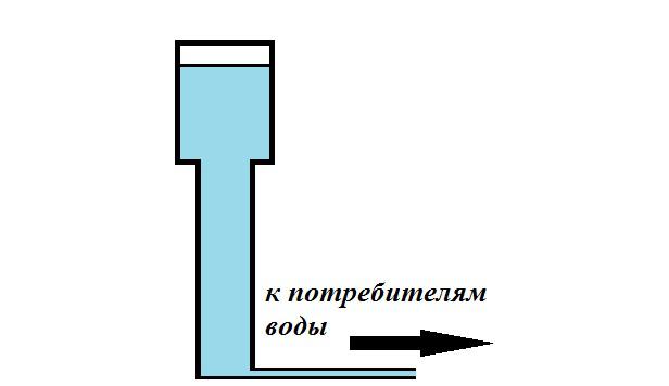
Вода оказывает максимальное давление на дно башни, когда башня заполнена полностью. Соответственно, чем меньше воды в башне, тем слабее давление и напор вытекающей из крана воды. Если открыть кран, вода будет постепенно вытекать сначала под сильным напором, а потом все медленнее, пока напор не ослабнет совсем. Здесь напряжение – это то давление, которое вода оказывает на дно. За уровень нулевого напряжения примем само дно башни.
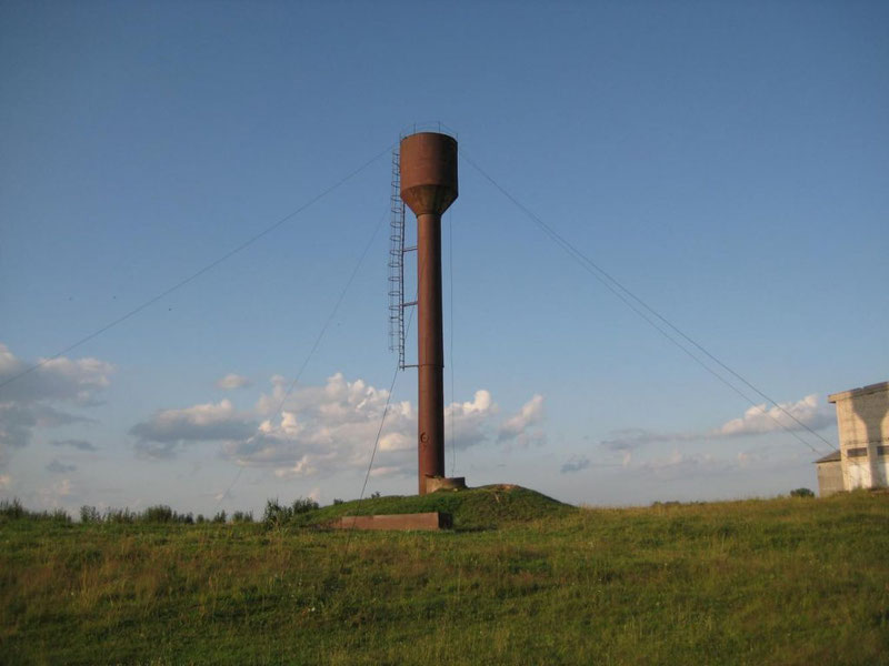
То же самое и с батарейкой. Сначала мы включаем наш источник тока (батарейку) в цепь, замыкая ее. Пусть это будут часы или фонарик. Пока уровень напряжения достаточный и батарейка не разрядилась, фонарик светит ярко, затем постепенно гаснет, пока не потухнет совсем.
Но как сделать так, чтобы напор не иссякал? Иными словами, как поддерживать в башне постоянный уровень воды, а на полюсах источника тока – постоянную разность потенциалов. По примеру башни ЭДС представляется как бы насосом, который обеспечивает приток в башню новой воды.
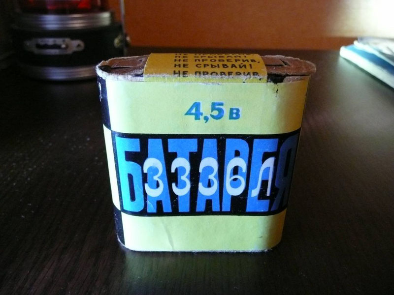
Природа ЭДС
Причина возникновения ЭДС в разных источниках тока разная. По природе возникновения различают следующие типы:
- Химическая ЭДС. Возникает в батарейках и аккумуляторах вследствие химических реакций.
- Термо ЭДС. Возникает, когда находящиеся при разных температурах контакты разнородных проводников соединены.
- ЭДС индукции. Возникает в генераторе при помещении вращающегося проводника в магнитное поле. ЭДС будет наводиться в проводнике, когда проводник пересекает силовые линии постоянного магнитного поля или когда магнитное поле изменяется по величине.
- Фотоэлектрическая ЭДС. Возникновению этой ЭДС способствует явление внешнего или внутреннего фотоэффекта.
- Пьезоэлектрическая ЭДС. ЭДС возникает при растяжении или сдавливании веществ.
Дорогие друзья, сегодня мы рассмотрели тему «ЭДС для чайников». Как видим, ЭДС – сила неэлектрического происхождения, которая поддерживает протекание электрического тока в цепи. Если Вы хотите узнать, как решаются задачи с ЭДС, советуем обратиться к нашим авторам – скрупулезно отобранным и проверенным специалистам, которые быстро и доходчиво разъяснят ход решения любой тематической задачи. И по традиции в конце предлагаем Вам посмотреть обучающее видео. Приятного просмотра и успехов в учебе!

Иван Колобков, известный также как Джони. Маркетолог, аналитик и копирайтер компании Zaochnik. Подающий надежды молодой писатель. Питает любовь к физике, раритетным вещам и творчеству Ч. Буковски.
Содержание:
- Определение и формула ЭДС
- Закон Ома для произвольного участка цепи
- Единицы измерения
- Примеры решения задач
Для поддержания электрического тока в проводнике длительное время, необходимо чтобы от конца проводника, имеющего меньший потенциал
(учтем, что носители тока предполагаются положительными зарядами) постоянно убирались доставляемые током заряды, при этом к концу с
большим потенциалом заряды постоянно подводились. То есть следует обеспечить круговорот зарядов. В этом круговороте заряды должны
перемещаться по замкнутому пути. Движение носителей тока при этом реализуется при помощи сил неэлектростатического происхождения.
Такие силы именуются сторонними. Получается, что для поддержания тока нужны сторонние силы, которые действуют на всем протяжении цепи
или на отдельных участках цепи.
Определение и формула ЭДС
Определение
Скалярная физическая величина, которая равна работе сторонних сил по перемещению единичного положительного заряда, называется
электродвижущей силой (ЭДС), действующей в цепи или на участке цепи. ЭДС обозначается
$varepsilon$ . Математически определение ЭДС запишем как:
$$varepsilon=frac{A}{q}(1)$$
где A – работа сторонних сил, q – заряд, над которым производится работа.
Электродвижущая сила источника численно равна разности потенциалов на концах элемента, если он разомкнут, что дает возможность измерить ЭДС по напряжению.
ЭДС, которая действует в замкнутой цепи, может бытьопределена как циркуляция вектора напряжённости сторонних сил:
$$varepsilon=oint_{L} bar{E}^{*} d bar{l}(2)$$
где $bar{E}^{*}$ — напряженность поля сторонних сил. Если напряженность поля сторонних
сил не равна нулю только в части цепи, например, на отрезке 1-2, тогда интегрирование в выражении (2) можно вести только по
данному участку. Соответственно, ЭДС, действующая на участке цепи 1-2 определяется как:
$$varepsilon=int_{1}^{2} bar{E}^{*} d bar{l}(3)$$
Формула (2) дает самое общее определение ЭДС, которое можно использовать для любых случаев.
Закон Ома для произвольного участка цепи
Участок цепи, на котором действуют сторонние силы, называют неоднородным. Для него выполняется равенство:
$$U_{12}=varphi_{1}-varphi_{2}+varepsilon_{12}(4)$$
где U12=IR21 – падение напряжения (или напряжение) на участке цепи 1-2 (I-сила тока);
$varphi_{1}-varphi_{2}$ – разность потенциалов концов участка;
$varepsilon_12$ – электродвижущая сила, которую содержит участок цепи.
$varepsilon_12$ равна алгебраической сумме ЭДС всех источников, которые находятся на данном участке.
Следует учитывать, что ЭДС может быть положительной и отрицательной. ЭДС называют положительной, если она увеличивает потенциал в
направлении тока (ток течет от минуса к плюсу источника).
Единицы измерения
Размерность ЭДС совпадает с размерностью потенциала. Основной единицей измерения ЭДС в системе СИ является: [$varepsilon$]=В
1В=1Дж/1Кл
Примеры решения задач
Пример
Задание. Электродвижущая сила элемента равна 10 В. Он создает в цепи силу тока равную 0,4 А.
Какова работа, которую совершают сторонние силы за 1 мин?
Решение. В качество основы для решения задачи используем формулу для вычисления ЭДС:
$$varepsilon=frac{A}{q}(1.1)$$
Заряд, который проходит в рассматриваемой цепи за 1 мин. можно найти как:
$$q=I Delta t(1.2)$$
Выразим из (1.1) работу, используем (1.2) для вычисления заряда, получим:
$$A=varepsilon I Delta t$$
Переведем время, данной в условиях задачи в секунды ($Delta t$ мин=60 с), проведем вычисления:
$A=10 cdot 0,4 cdot 60=240$ (Дж)
Ответ. A=240 Дж

236
проверенных автора готовы помочь в написании работы любой сложности
Мы помогли уже 4 396 ученикам и студентам сдать работы от решения задач до дипломных на отлично! Узнай стоимость своей работы за 15 минут!
Пример
Задание. Металлический диск, имеющий радиус a, вращается с угловой скоростью
$omega$, включен в электрическую цепь при
помощи скользящих контактов, которые касаются оси диска и его окружности (рис.1). Какой будет ЭДС, которая появится между осью
диска и его наружным краем?
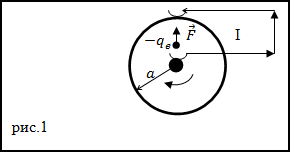
Решение. В условиях, которые описаны в задаче, на каждый электрон проводника действует центробежная сила (F)
которая является сторонней. Вследствие ее действия, в диске возникает ЭДС и между осью диска и его наружным краем появляется напряжение.
Формулу для вычисления центробежной силы запишем как:
$$F=m r omega^{2}(2.1)$$
где m – масса электрона, r – расстояние от оси диска.Fдействует на заряженную частицу (электрон), следовательноучитывая (2.1), имеем:
$$E^{*}=frac{F}{q}=frac{m r omega^{2}}{q}$$
где q – заряд электрона.
В соответствии с формулой, определяющей ЭДС участка цепи, получаем:
$$varepsilon=int_{1}^{2} bar{E} d bar{l}=int_{0}^{a} E^{*} d r=int_{0}^{a} frac{m r omega^{2}}{q} d r=frac{m r omega^{2} a^{2}}{2 q}$$
Ответ. $varepsilon=frac{m r omega^{2} a^{2}}{2 q}$
Читать дальше: Формулы по физике.
Электродвижущая сила или сокращено ЭДС – это способность источника тока ил по-другому питающий элемент, создавать в электрической цепи разность потенциалов. Элементами питания являются аккумуляторы или батареи. Это скалярная физическая величина, равная работе сторонних сил для перемещения одного заряда с положительной величиной. В данной статье будут рассмотрены теоритические вопросы ЭДС, как она образуется, а также для чего она может быть использована на практике и где используются, а главное как рассчитать ее.

Что такое ЭДС: объяснение простыми словами
Под ЭДС понимается удельная работа сторонних сил по перемещению единичного заряда в контуре электрической цепи. Это понятие в электричестве предполагает множество физических толкований, относящихся к различным областям технических знаний. В электротехнике — это удельная работа сторонних сил, появляющаяся в индуктивных обмотках при наведении в них переменного поля. В химии она означает разность потенциалов, возникающее при электролизе, а также при реакциях, сопровождающихся разделением электрических зарядов.
В физике она соответствует электродвижущей силе, создаваемой на концах электрической термопары, например. Чтобы объяснить суть ЭДС простыми словами – потребуется рассмотреть каждый из вариантов ее трактовки. Прежде чем перейти к основной части статьи отметим, что ЭДС и напряжение очень близкие по смыслу понятия, но всё же несколько отличаются. Если сказать кратко, то ЭДС — на источнике питания без нагрузки, а когда к нему подключают нагрузку — это уже напряжение. Потому что количество вольт на ИП под нагрузкой почти всегда несколько меньше, чем без неё. Это связано с наличием внутреннего сопротивления таких источников питания, как трансформаторы и гальванические элементы.
Дополнительный материал по теме: Простыми словами о преобразователях напряжения.
Электродвижущая сила (эдс), физическая величина, характеризующая действие сторонних (непотенциальных) сил в источниках постоянного или переменного тока; в замкнутом проводящем контуре равна работе этих сил по перемещению единичного положительного заряда вдоль контура. Если через Eстр обозначить напряжённость поля сторонних сил, то эдс в замкнутом контуре (L) равна , где dl — элемент длины контура. Потенциальные силы электростатического (или стационарного) поля не могут поддерживать постоянный ток в цепи, т. к. работа этих сил на замкнутом пути равна нулю. Прохождение же тока по проводникам сопровождается выделением энергии — нагреванием проводников.
Сторонние силы приводят в движение заряженные частицы внутри источников тока: генераторов, гальванических элементов, аккумуляторов и т. д. Происхождение сторонних сил может быть различным. В генераторах сторонние силы — это силы со стороны вихревого электрического поля, возникающего при изменении магнитного поля со временем, или Лоренца сила, действующая со стороны магнитного поля на электроны в движущемся проводнике; в гальванических элементах и аккумуляторах — это химические силы и т. д. Эдс определяет силу тока в цепи при заданном её сопротивлении (см. Ома закон). Измеряется эдс, как и напряжение, в вольтах.
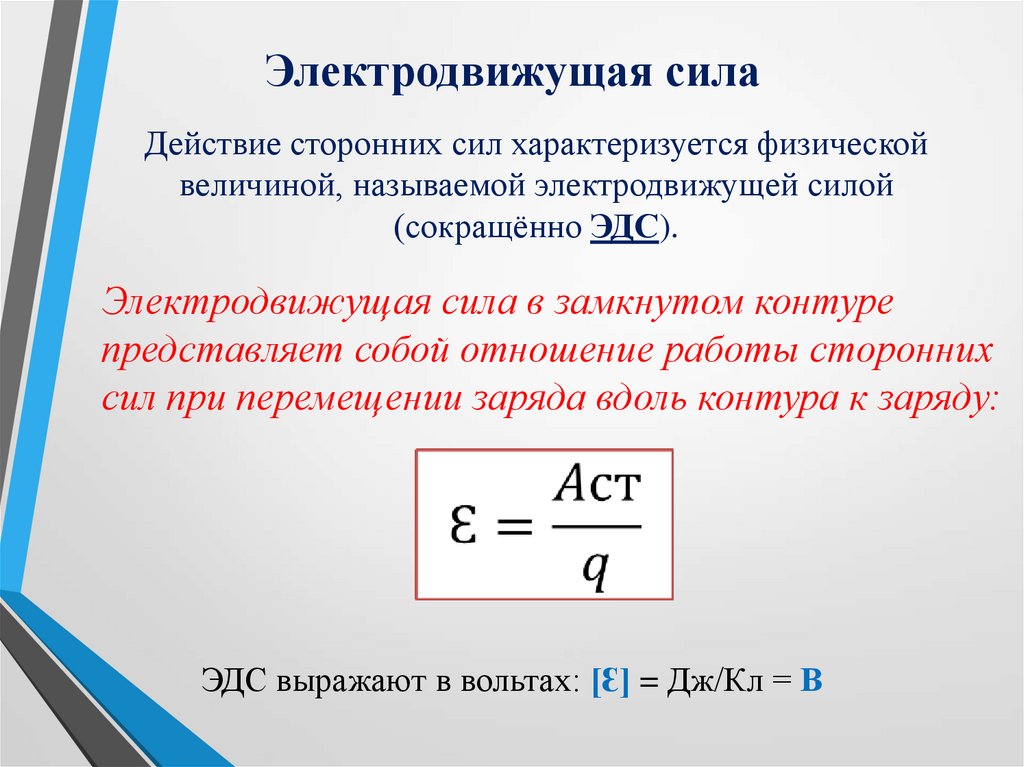
Природа ЭДС
Причина возникновения ЭДС в разных источниках тока разная. По природе возникновения различают следующие типы:
- Химическая ЭДС. Возникает в батарейках и аккумуляторах вследствие химических реакций.
- Термо ЭДС. Возникает, когда находящиеся при разных температурах контакты разнородных проводников соединены.
- ЭДС индукции. Возникает в генераторе при помещении вращающегося проводника в магнитное поле. ЭДС будет наводиться в проводнике, когда проводник пересекает силовые линии постоянного магнитного поля или когда магнитное поле изменяется по величине.
- Фотоэлектрическая ЭДС. Возникновению этой ЭДС способствует явление внешнего или внутреннего фотоэффекта.
- Пьезоэлектрическая ЭДС. ЭДС возникает при растяжении или сдавливании веществ.
Электромагнитная индукция (самоиндукция)
Начнем с электромагнитной индукции. Это явление описывает закон электромагнитной индукции Фарадея. Физический смысл этого явления состоит в способности электромагнитного поля наводить ЭДС в находящемся рядом проводнике. При этом или поле должно изменяться, например, по величине и направлению векторов, или перемещаться относительно проводника, или должен двигаться проводник относительно этого поля. На концах проводника в этом случае возникает разность потенциалов.
Опыт демонстрирует появление ЭДС в катушке при воздействии изменяющегося магнитного поля постоянного магнита. Есть и другое похожее по смыслу явление — взаимоиндукция. Оно заключается в том, что изменение направления и силы тока одной катушки индуцирует ЭДС на выводах расположенной рядом катушки, широко применяется в различных областях техники, включая электрику и электронику. Оно лежит в основе работы трансформаторов, где магнитный поток одной обмотки наводит ток и напряжение во второй.
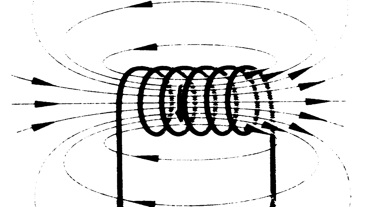
В электрике физический эффект под названием ЭДС используется при изготовлении специальных преобразователей переменного тока, обеспечивающих получение нужных значений действующих величин (тока и напряжения). Благодаря явлениям индукции и самоиндукции инженерам удалось разработать множество электротехнических устройств: от обычной катушки индуктивности (дросселя) и вплоть до трансформатора. Понятие взаимоиндукции касается только переменного тока, при протекании которого в контуре или проводнике меняется магнитный поток.
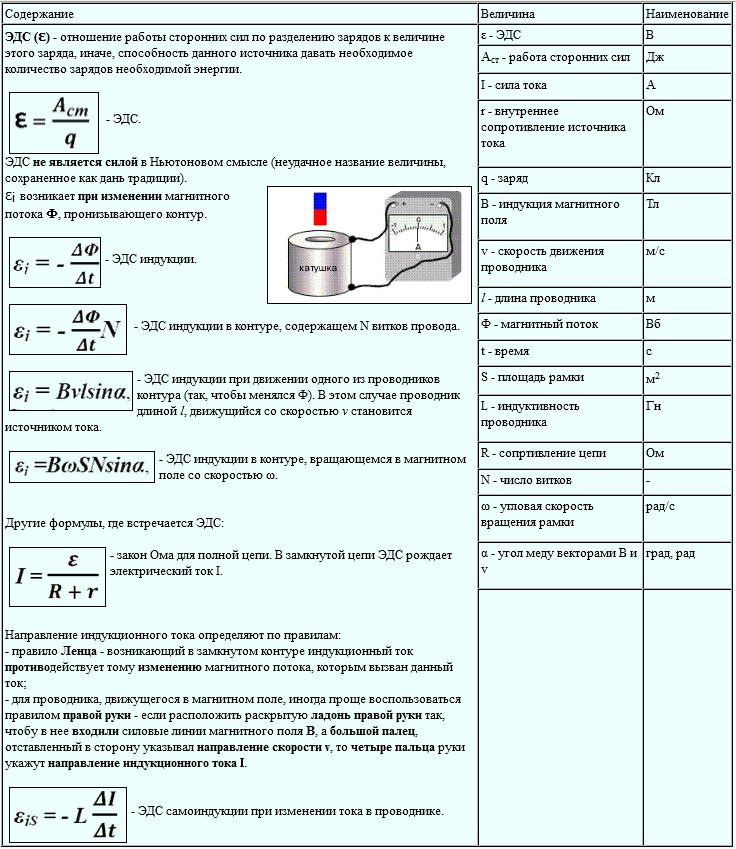
ЭДС в быту и единицы измерения
Другие примеры встречаются в практической жизни любого рядового человека. Под эту категорию попадают такие привычные вещи, как малогабаритные батарейки, а также другие миниатюрные элементы питания. В этом случае рабочая ЭДС формируется за счет химических процессов, протекающих внутри источников постоянного напряжения. Когда оно возникает на клеммах (полюсах) батареи вследствие внутренних изменений – элемент полностью готов к работе. Со временем величина ЭДС несколько снижается, а внутреннее сопротивление заметно возрастает.
В результате если вы измеряете напряжение на не подключенной ни к чему пальчиковой батарейке вы видите нормальные для неё 1.5В (или около того), но когда к батарейке подключается нагрузка, допустим, вы установили её в какой-то прибор — он не работает. Почему? Потому что если предположить, что у вольтметра внутреннее сопротивление во много раз выше, чем внутреннее сопротивлении батарейки — то вы измеряли её ЭДС. Когда батарейка начала отдавать ток в нагрузке на её выводах стало не 1.5В, а, допустим, 1.2В — прибору недостаточно ни напряжения, ни тока для нормальной работы.
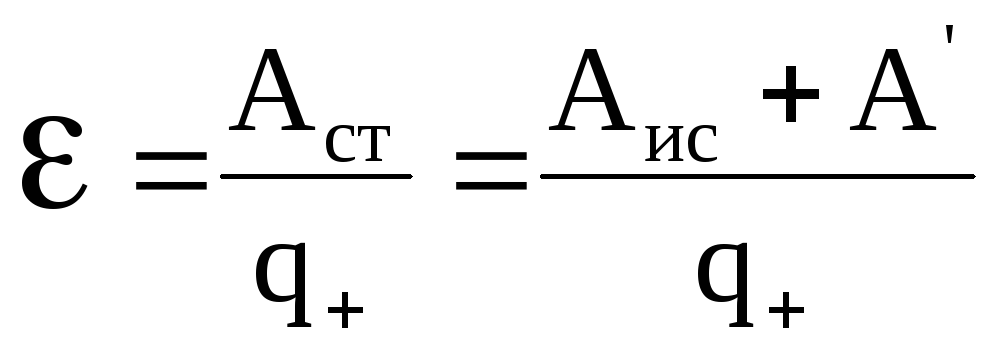
Как раз вот эти 0.3 В и упали на внутреннем сопротивлении гальванического элемента. Если батарейка совсем старая и её электроды разрушены, то на клеммах батареи может не быть вообще никакой электродвижущей силы или напряжения — т.е. ноль. Совсем небольшая по величине электродвижущая сила наводится и в рамках антенны приемника, которая усиливается затем специальными каскадами, и мы получаем наш телевизионный, радио и даже Wi-Fi сигнал.
Материал по теме: Выбираем цифро-аналоговый преобразователь.
Как образуется ЭДС
Идеальный источник ЭДС – генератор, внутреннее сопротивление которого равно нулю, а напряжение на его зажимах не зависит от нагрузки. Мощность идеального источника ЭДС бесконечна. Реальный источник ЭДС, в отличие от идеального, содержит внутреннее сопротивление Ri и его напряжение зависит от нагрузки (рис. 1., б), а мощность источника конечна. Электрическая схема реального генератора ЭДС представляет собой последовательное соединение идеального генератора ЭДС Е и его внутреннего сопротивления Ri.
На практике для того чтобы приблизить режим работы реального генератора ЭДС к режиму работы идеального, внутреннее сопротивление реального генератора Ri стараются делать как можно меньше, а сопротивление нагрузки Rн необходимо подключать величиной не менее чем в 10 раз большей величины внутреннего сопротивления генератора, т.е. необходимо выполнять условие: Rн >> Ri
Для того чтобы выходное напряжение реального генератора ЭДС не зависело от нагрузки, его стабилизируют применением специальных электронных схем стабилизации напряжения. Поскольку внутреннее сопротивление реального генератора ЭДС не может быть выполнено бесконечно малым, его минимизируют и выполняют стандартным для возможности согласованного подключения к нему потребителей энергии. В радиотехнике величины стандартного выходного сопротивления генераторов ЭДС составляют 50 Ом (промышленный стандарт) и 75 Ом (бытовой стандарт).
Например, все телевизионные приемники имеют входное сопротивление 75 Ом и подключены к антеннам коаксиальным кабелем именно такого волнового сопротивления. Для приближения к идеальным генераторам ЭДС источники питающего напряжения, используемые во всей промышленной и бытовой радиоэлектронной аппаратуре, выполняют с применением специальных электронных схем стабилизации выходного напряжения, которые позволяют выдерживать практически неизменное выходное напряжение источника питания в заданном диапазоне токов, потребляемых от источника ЭДС (иногда его называют источником напряжения).
На электрических схемах источники ЭДС изображаются так: Е — источник постоянной ЭДС, е(t) – источник гармонической (переменной) ЭДС в форме функции времени. Электродвижущая сила Е батареи последовательно соединенных одинаковых элементов равна электродвижущей силе одного элемента Е, умноженной на число элементов n батареи: Е = nЕ.
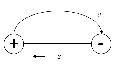
Электродвижущая сила (ЭДС) источника энергии
Для поддержания электрического тока в проводнике требуется внешний источник энергии, создающий все время разность потенциалов между концами этого проводника. Такие источники энергии получили название источников электрической энергии (или источников тока). Источники электрической энергии обладают определенной электродвижущей силой (сокращенно ЭДС), которая создает и длительное время поддерживает разность потенциалов между концами проводника.

Инженер по специальности «Программное обеспечение вычислительной техники и автоматизированных систем», МИФИ, 2005–2010 гг.
Задать вопрос
Иногда говорят, что ЭДС создает электрический ток в цепи. Нужно помнить об условности такого определения, так как выше мы уже установили, что причина возникновения и существования электрического тока — электрическое поле.
Источник электрической энергии производит определенную работу, перемещая электрические заряды по всей замкнутой цепи. За единицу измерения электродвижущей силы принят вольт (сокращенно вольт обозначается буквой В или V — «вэ» латинское). ЭДС источника электрической энергии равна одному вольту, если при перемещении одного кулона электричества по всей замкнутой, цепи источник электрической энергии совершает работу, равную одному джоулю:
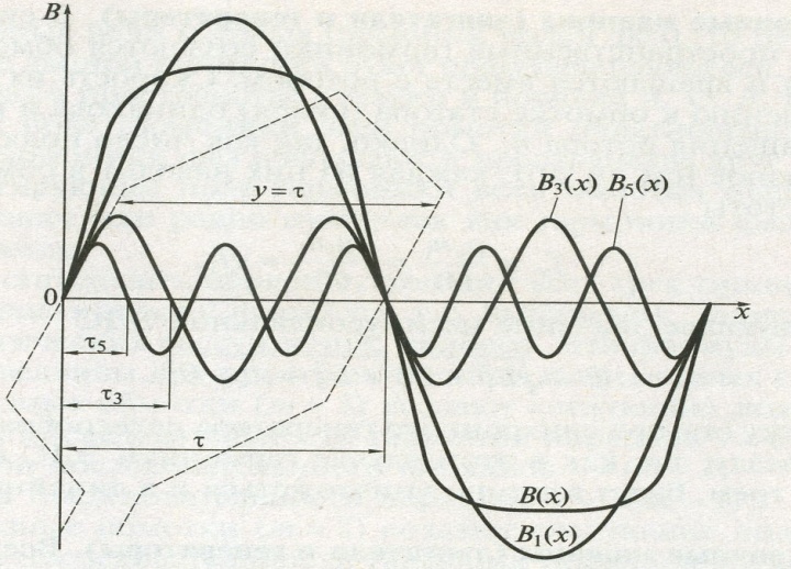
В практике для измерения ЭДС используются как более крупные, так и более мелкие единицы, а именно:
- 1 киловольт (кВ, kV), равный 1000 В;
- 1 милливольт (мВ, mV), равный одной тысячной доле вольта (10-3 В),
- 1 микровольт (мкВ, μV), равный одной миллионной доле вольта (10-6 В).
Очевидно, что 1 кВ = 1000 В; 1 В = 1000 мВ = 1 000 000 мкВ; 1 мВ= 1000 мкВ.
В настоящее, время существует несколько видов источников электрической энергии. Впервые в качестве источника электрической энергии была использована гальваническая батарея, состоящая из нескольких цинковых и медных кружков, между которыми была проложена кожа, смоченная в подкисленной воде. В гальванической батарее химическая энергия превращалась в электрическую (подробнее об этом будет рассказано в главе XVI). Свое название гальваническая батарея получила по имени итальянского физиолога Луиджи Гальвани (1737—1798), одного из основателей учения об электричестве.
Многочисленные опыты по усовершенствованию и практическому использованию гальванических батарей были проведены русским ученым Василием Владимировичем Петровым. Еще в начале прошлого века он создал самую большую в мире гальваническую батарею и использовал ее для ряда блестящих опытов. Источники электрической энергии, работающие по принципу преобразования химической энергии в электрическую, называются химическими источниками электрической энергии.
Полезно знать: Как рассчитать мощность электрического тока.
Другим основным источником электрической энергий, получившим широкое применение в электротехнике и радиотехнике, является генератор. В генераторах механическая энергия преобразуется в электрическую. У химических источников электрической энергии и у генераторов электродвижущая сила проявляется одинаково, создавая на зажимах источника разность потенциалов и поддерживая ее длительное время.
[stextbox id=’info’]Эти зажимы называются полюсами источника электрической энергии. Один полюс источника электрической энергии имеет положительный потенциал (недостаток электронов), обозначается знаком плюс ( + ) и называется положительным полюсом. [/stextbox]
Другой полюс имеет отрицательный потенциал (избыток электронов), обозначается знаком минус (—) и называется отрицательным полюсом. От источников электрической энергии электрическая энергия передается по проводам к ее потребителям (электрические лампы, электродвигатели, электрические дуги, электронагревательные приборы и т. д.).
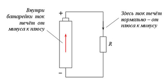
Примеры решения задач
К каждой позиции первого столбца подберите соответствующую позицию второго:
Решение: Электродвижущая сила гальванического элемента есть величина, численно равная работе сторонних сил при перемещении единичного положительного заряда внутри элемента от одного полюса к другому.
Работа сторонних сил не может быть выражена через разность потенциалов, так как сторонние силы непотенциальны и их работа зависит от формы траектории перемещения зарядов.
ЭДС определяется по формуле:

Сила тока определяется по формуле:

Сопротивление определяется по формуле:

Разность потенциалов определяется по формуле:

Правильный ответ:
Что такое электродвижущая сила?
Это отношение работы сторонних сил при перемещении заряда по замкнутому контуру к абсолютной величине этого заряда.
Что такое электрическая цепь?
Набор устройств, которые соединены проводниками, предназначенный для протекания тока.
Как звучит закон Ома для полной цепи?
Сила тока в полной цепи равна отношению ЭДС цепи к ее полному сопротивлению.
Заключение
Инженер по специальности «Программное обеспечение вычислительной техники и автоматизированных систем», МИФИ, 2005–2010 гг.
Задать вопрос
Если в проводнике создать электрическое поле и не поддерживать это поле, то перемещение носителей тока приведет к тому, что поле внутри проводника исчезнет, и ток прекратится. Для того чтобы поддерживать ток в цепи достаточно долго, необходимо осуществить движение зарядов по замкнутой траектории, то есть сделать линии постоянного тока замкнутыми. Следовательно, в замкнутой цепи должны быть участки, на которых носители заряда будут двигаться против сил электростатического поля, то есть от точек с меньшим потенциалом к точкам с большим потенциалом. Это возможно лишь при наличии неэлектрических сил, называемых сторонними силами. Сторонними силами являются силы любой природы, кроме кулоновских.
Дополнительную информацию о предмете статьи можно узнать из файла «Электродвижущая сила в цепях электрического тока». А также в нашей группе ВК публикуются интересные материалы, с которыми вы можете познакомиться первыми. Для этого приглашаем читателей подписаться и вступить в группу.
В завершение хочу выразить благодарность источникам, откуда почерпнут материал для подготовки статьи:
www.booksite.ru
www.scsiexplorer.com.ua
www.samelectrik.ru
www.electricalschool.info
www.sxemotehnika.ru
www.zaochnik.ru
www.ido.tsu.ru
Предыдущая
ТеорияЧто такое термопара: об устройстве простыми словами
Следующая
ТеорияЧто такое заземление простыми словами
У этого термина существуют и другие значения, см. Сила (значения).
| Классическая электродинамика |
|---|
 |
| Электричество · Магнетизм |
|
Электростатика Закон Кулона |
|
Магнитостатика Закон Био — Савара — Лапласа |
|
Электродинамика Векторный потенциал |
|
Электрическая цепь Закон Ома |
|
Ковариантная формулировка Тензор электромагнитного поля |
| См. также: Портал:Физика |
Электродвижущая сила (ЭДС) — скалярная физическая величина, характеризующая работу сторонних сил (то есть любых сил, кроме электростатических и диссипативных), действующих в квазистационарных цепях постоянного или переменного тока. В замкнутом проводящем контуре ЭДС равна работе этих сил по перемещению единичного положительного заряда вдоль всего контура[1][2].
По аналогии с напряжённостью электрического поля вводят понятие напряжённость сторонних сил  , под которой понимают векторную физическую величину, равную отношению сторонней силы, действующей на пробный электрический заряд к величине этого заряда. Тогда в замкнутом контуре ЭДС будет равна:
- ,

где  — элемент контура.
Несмотря на наличие слова «сила» в наименовании понятия, электродвижущая сила не является одной из сил в физике и не имеет размерности силы.
ЭДС так же, как и напряжение, в Международной системе единиц (СИ) измеряется в вольтах.
Можно говорить об электродвижущей силе на любом участке цепи. Это удельная работа сторонних сил не во всем контуре, а только на данном участке. ЭДС гальванического элемента есть работа сторонних сил при перемещении единичного положительного заряда внутри элемента от одного полюса к другому. Работа сторонних сил не может быть выражена через разность потенциалов, так как сторонние силы непотенциальны и их работа зависит от формы траектории. Так, например, работа сторонних сил при перемещении заряда между клеммами источника тока вне самого́ источника равна нулю.
ЭДС и закон Ома
Электродвижущая сила источника связана с электрическим током, протекающим в цепи, соотношениями закона Ома. Закон Ома для неоднородного участка цепи имеет вид[1]

где  — разность между значениями потенциала в начале и в конце участка цепи, — сила тока, текущего по участку, а — сопротивление участка.
Если точки 1 и 2 совпадают (цепь замкнута), то  и предыдущая формула переходит в формулу закона Ома для замкнутой цепи[1]:

где теперь — полное сопротивление всей цепи.
В общем случае полное сопротивление цепи складывается из сопротивления внешнего по отношению к источнику тока участка цепи ( ) и внутреннего сопротивления самого́ источника тока (
 ). С учётом этого следует:

ЭДС источника тока
Если на участке цепи не действуют сторонние силы (однородный участок цепи) и, значит, источника тока на нём нет, то, как это следует из закона Ома для неоднородного участка цепи, выполняется:

Значит, если в качестве точки 1 выбрать анод источника, а в качестве точки 2 — его катод, то для разности между потенциалами анода  и катода
  можно записать:

где как и ранее — сопротивление внешнего участка цепи.
Поделив данное соотношение на закон Ома для замкнутой цепи, записанный в виде  , мы получим:
- и затем


Из последнего соотношения следуют два вывода:
- Во всех случаях, когда по цепи течёт ток, разность потенциалов между клеммами источника тока меньше, чем ЭДС источника.
- В предельном случае, когда бесконечно (цепь разорвана), выполняется


Таким образом, ЭДС источника тока равна разности потенциалов между его клеммами в состоянии, когда источник отключён от цепи[1].
ЭДС индукции
Причиной возникновения электродвижущей силы в замкнутом контуре может стать изменение потока магнитного поля, пронизывающего поверхность, ограниченную данным контуром. Это явление называется электромагнитной индукцией. Величина ЭДС индукции в контуре определяется выражением

где  — поток магнитного поля через указанную поверхность. Знак «−» перед выражением показывает, что индукционный ток, созданный ЭДС индукции, препятствует изменению магнитного потока в контуре (см. правило Ленца). В свою очередь причиной изменения магнитного потока может быть как изменение магнитного поля, так и движение контура в целом или его отдельных частей.
Неэлектростатический характер ЭДС

Внутри источника ЭДС ток течёт в направлении, противоположном нормальному. Это невозможно без дополнительной силы неэлектростатической природы, преодолевающей силу электрического отталкивания
Как показано на рисунке, электрический ток, нормальное направление которого — от «плюса» к «минусу», внутри источника ЭДС (например, внутри гальванического элемента) течёт в противоположном направлении. Направление от «плюса» к «минусу» совпадает с направлением электростатической силы, действующей на положительные заряды. Поэтому для того, чтобы заставить ток течь в противоположном направлении, необходима дополнительная сила неэлектростатической природы (центробежная сила, сила Лоренца, силы химической природы, сила со стороны вихревого электрического поля) которая бы преодолевала силу со стороны электростатического поля. Диссипативные силы, хотя и противодействуют электростатическому полю, не могут заставить ток течь в противоположном направлении, поэтому они не входят в состав сторонних сил, работа которых используется в определении ЭДС.
Сторонние силы
Сторонними силами называются силы, вызывающие перемещение электрических зарядов внутри источника постоянного тока против направления действия сил электростатического поля. Например, в гальваническом элементе или аккумуляторе сторонние силы возникают в результате электрохимических процессов, происходящих на границе соприкосновения электрода с электролитом; в электрическом генераторе постоянного тока сторонней силой является сила Лоренца[3].
См. также
- Правила Кирхгофа
Примечания
- ↑ 1 2 3 4 Сивухин Д. В. Общий курс физики. — М.: Физматлит, МФТИ, 2004. — Т. III. Электричество. — С. 193—194. — 656 с. — ISBN 5-9221-0227-3.
- ↑ Калашников С. Г. Общий курс физики. — М.: Гостехтеориздат, 1956. — Т. II. Электричество. — С. 146, 153. — 664 с.
- ↑ Кабардин О. Ф. Физика. — М., Просвещение, 1985. — Тираж 754 000 экз. — с. 131
![]()
Эта страница в последний раз была отредактирована 4 марта 2023 в 04:21.
Как только страница обновилась в Википедии она обновляется в Вики 2.
Обычно почти сразу, изредка в течении часа.