Время на прочтение
4 мин
Количество просмотров 199K
В работе со студентами и учениками я заметила, что при изучении какого-либо языка программирования большой интерес вызывает работа с графикой. Даже те студенты, которые скучали на заданиях про числа Фибоначчи, и уже казалось бы у них пропадал интерес к изучению языка, активизировались на темах, связанных с графикой.
Поэтому предлагаю потренироваться в написании небольшой графической програмки на Python с использованием tkinter (кроссплатформенная библиотека для разработки графического интерфейса на языке Python).
Код в этой статье написан для Python 3.5.
Задание: написание программы для рисования на холсте произвольного размера кругов разных цветов.
Не сложно, возможно программа «детская», но я думаю, для яркой иллюстрации того, что может tkinter самое оно.
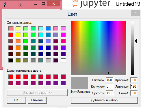
Хочу рассказать сначала о том, как указать цвет. Конечно удобным для компьютера способом. Для этого в tkinter есть специальный инструмент, который можно запустить таким образом:
from tkinter import *
window = Tk()
colorchooser.askcolor()
Пояснения к коду:
- rom tkinter import * — импорт библиотеки, вернее всех ее методов, на что указывает звездочка (*);
- window = Tk() — создание окна tkinter;
- colorchooser.askcolor() — открывает окно выбора цвета и возвращает кортеж из двух значений: кортеж из трех элементов, интенсивность каждой RGB цвета, и строка. цвет в шестнадцатиричной системе.
Примечание: как сказано в коментариях ниже — звёздочка не все импортирует, надёжнее будет написать
from tkinter import colorchooser
Можно для определения цвета рисования использовать английские название цветов. Здесь хочу заметить, что не все они поддерживаются. Тут говорится, что без проблем вы можете использовать цвета «white», «black», «red», «green», «blue», «cyan», «yellow», «magenta». Но я все таки поэкспериментировала, и вы увидите дальше, что из этого вышло.
Для того, чтобы рисовать в Python необходимо создать холст. Для рисования используется система координат х и у, где точка (0, 0) находится в верхнем левом углу.
В общем хватит вступлений — начнем.
from random import *
from tkinter import *

size = 600
root = Tk()
canvas = Canvas(root, width=size, height=size)
canvas.pack()
diapason = 0
Пояснения к коду:
- from random import * — импорт всех методов модуля random;
- from tkinter import * — это вы уже знаете;
- переменная size понадобится потом;
- root = Tk() — создаем окно;
- canvas = Canvas(root, width=size, height=size) — создаем холст, используя значение переменной size (вот она и понадобилась);
- canvas.pack() — указание расположить холст внутри окна;
- переменная diapason понадобится потом для использования в условии цикла.
Дальше создаем цикл:
while diapason < 1000:
    colors = choice(['aqua', 'blue', 'fuchsia', 'green', 'maroon', 'orange',
                  'pink', 'purple', 'red','yellow', 'violet', 'indigo', 'chartreuse', 'lime', ''#f55c4b''])
    x0 = randint(0, size)
    y0 = randint(0, size)
    d = randint(0, size/5)
    canvas.create_oval(x0, y0, x0+d, y0+d, fill=colors)
    root.update()
    diapason += 1
Пояснения к коду:
- while diapason < 1000: — с предусловием, которое говорит о том, что цикл будет повторятся пока переменная diapason не дойдет до 1000.
colors = choice(['aqua', 'blue', 'fuchsia', 'green', 'maroon', 'orange',
                  'pink', 'purple', 'red','yellow', 'violet', 'indigo', 'chartreuse', 'lime', ''#f55c4b''])
Создаем список для якобы случайного выбора цвета кругов. Заметьте, что один из цветов написан в формате »#f55c4b» — код цвета в шестнадцатиричной системе.
Здесь хочу остановиться на выборе цвета. Мне хотелось добавить как можно больше вариантов выбора цвета, поэтому я воспользовалась таблицей названий цветов в английском языке. Но вскоре поняла, что многие английские названия не поддерживаются — программа переставала работать. Поэтому определение цвета в шестнадцатиричной системе будет для этих целей более подходящим вариантом.
x0 = randint(0, size) и y0 = randint(0, size) — случайный выбор координат х и у в рамках холста размером size.
d randint(0, size/5) — произвольный выбор размера круга, ограниченный size/5.
canvas.create_oval(x0, y0, x0+d, y0+d, fill=colors) — собственно говоря рисуем круги, в точках с координатами x0 и y0, размерами по вертикали и горизонтали x0+d и y0+d, заливкой цветом, который выбирается случайным образом из списка colors.
root.update() — update() — обрабатывает все задачи, стоящие в очереди. Обычно эта функция используется во время «тяжёлых» расчётов, когда необходимо чтобы приложение оставалось отзывчивым на действия пользователя.
Без этого в итоге отобразятся круги, но процесс их появления будет вам не виден. А именно это придает шарм этой програмке.
diapason += 1 — шаг цикла, счетчик.
В результате получается такая картинка:
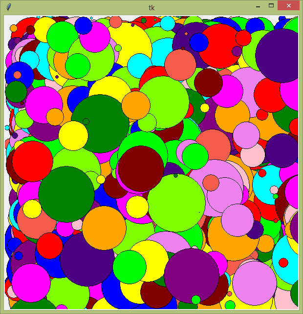
Мне не понравилось, что справа и вверху какие-то пустые места образовываются, поэтому я немного изменила условие цикла while diapason < 2000 или 3000. Так холст получился более заполненным.
Также можно сделать цикл бесконечным:
while True:
    colors = choicecolors = choice(['aqua', 'blue', 'fuchsia', 'green', 'maroon', 'orange',
                  'pink', 'purple', 'red','yellow', 'violet', 'indigo', 'chartreuse', 'lime'])
    x0 = randint(0, size)
    y0 = randint(0, size)
    d = randint(0, size/5)
    canvas.create_oval(x0, y0, x0+d, y0+d, fill=colors )
    root.update()
Вот как-то так оно происходит: instagram.com/p/8fcGynPlEc
Я думаю, можно было бы еще поиграться со скоростью рисования кругов или их движением по холсту. Можно было увеличить варианты выбора цветов. Поставить условие для остановки бесконечного цикла, например по нажатию пробела. Это все задания для будущих программ.
Студенты еще спросили, а можно ли запускать это как заставку на рабочем столе Windows? Пока не нашла как это можно было бы сделать.
Источники:
Документация по python http://www.ilnurgi1.ru/docs/python/modules/tkinter/colorchooser.html
Курс по библиотеке Tkinter языка Python
Помощники:
Введение в Tkinter http://habrahabr.ru/post/133337
Создание GUI на Python с помощью библиотеки Tkinter. Программирование для начинающих http://younglinux.info/book/export/html/48
Таблица названий цветов в английском языке http://www.falsefriends.ru/english-colors.htm
Приветствую всех, ниже я продемонстрирую вариант того как можно реализовать простенькую программу для рисования на C#
Шаг 1:
Создаем проект Windows Form приложения.
Шаг 2:
Мы будем использовать события формы, MouseMove, MouseDown и MouseUp.
Шаг 3:
Исходный код программы:
|
1 2 3 4 5 6 7 8 9 10 11 12 13 14 15 16 17 18 19 20 21 22 23 24 25 26 27 28 29 30 31 32 33 34 35 36 37 38 39 40 41 42 43 44 45 46 47 48 49 50 51 52 53 54 |
using System; using System.Collections.Generic; using System.ComponentModel; using System.Data; using System.Drawing; using System.Linq; using System.Text; using System.Threading.Tasks; using System.Windows.Forms; namespace Приложения_для_рисования { public partial class Form1 : Form //www.nookery.ru { public Form1() { InitializeComponent(); } bool drw; int beginX, beginY; private void Form1_MouseUp(object sender, MouseEventArgs e) { drw = false; } private void Form1_MouseDown(object sender, MouseEventArgs e) { drw = true; beginX = e.X; beginY = e.Y; } private void Form1_MouseMove(object sender, MouseEventArgs e) { Graphics g = this.CreateGraphics(); Pen p = new Pen(Color.White, 4); Point point1 = new Point(beginX, beginY); Point point2 = new Point(e.X, e.Y); if (drw == true) { g.DrawLine(p, point1, point2); beginX = e.X; beginY = e.Y; } } private void Form1_Load(object sender, EventArgs e) { this.Text = «www.nookery.ru»; this.BackColor = Color.Black; } } } |
Russian (Pусский) translation by Elen (you can also view the original English article)
В серии нескольких статье мы создадим приложение для рисования с помощью пальцев для Android, использующее сенсорное взаимодействие. У пользователя будет возможность выбирать цвет из цветовой палитры, размер кисти, стирать, создавать новый рисунок или сохранять уже существующий в галерее устройства.
Формат урока
Данный урок по созданию приложения для рисования будет состоять из трех частей:
- Создание интерфейса
- Сенсорное взаимодействие
- Основные функции
Просмотр конечного результата


В первой части серии нескольких уроков мы создадим пользовательский интерфейс. Во второй части мы осуществим рисование на холсте и выбор цветов. В заключительной части мы представим возможность стирать, создавать новые рисунки и сохранять их в галерее пользовательского устройства. Мы рассмотрим опции, которые вы сможете использовать для улучшения этого приложения, проходя в будущем другие учебные материалы, включая заливку холста, прозрачность и другое взаимодействие, отличное от сенсорного.
1. Подготовка к рисованию
Шаг 1
В прошлый раз мы создали класс с именем «DrawingView», который представляет собой пользовательский View для функций рисования, которые должны выполняться внутри. Мы создали схему объявления класса и метод с именем «setupDrawing» — вот сейчас мы сделаем это. В своем классе DrawingView добавьте следующие операторы импорта:
import android.graphics.Bitmap;
import android.graphics.Canvas;
import android.graphics.Paint;
import android.graphics.Path;
import android.view.MotionEvent;
Затем добавьте некоторые переменные экземпляра в верхней части класса:
//drawing path
private Path drawPath;
//drawing and canvas paint
private Paint drawPaint, canvasPaint;
//initial color
private int paintColor = 0xFF660000;
//canvas
private Canvas drawCanvas;
//canvas bitmap
private Bitmap canvasBitmap;
Когда пользователь прикасается к экрану и перемещает палец, чтоб рисовать, мы будем использовать Path для отслеживания его действий рисования на холсте. Как холст, так и рисунок поверх него представлены объектами Paint. Начальный цвет краски соответствует первому цвету в палитре, которую мы создали в последний раз, и которая будет первоначально выбрана при запуске приложения. Наконец, мы объявляем переменные для холста и растрового изображения: пути пользователя, нарисованные с помощью drawPaint, будут нарисованы на холсте, который нарисован canvasPaint.
Шаг 2
Давайте создадим в методе setupDrawing некоторые из этих переменных, чтобы установить класс для рисования. Сначала создайте объекты рисования Path и Paint:
drawPath = new Path();
drawPaint = new Paint();
Затем установите начальный цвет:
drawPaint.setColor(paintColor);
Теперь задайте начальные свойства пути:
drawPaint.setAntiAlias(true);
drawPaint.setStrokeWidth(20);
drawPaint.setStyle(Paint.Style.STROKE);
drawPaint.setStrokeJoin(Paint.Join.ROUND);
drawPaint.setStrokeCap(Paint.Cap.ROUND);
Мы изменим часть этого кода в следующем уроке, когда реализуем возможность выбора размеров кистей; пока мы установим произвольный размер кисти. Настройка сглаживания, штрихов и стилей сделает рисунки пользователя более гладкими.
Завершите метод setupDrawing, создав экземпляр объекта Paint:
canvasPaint = new Paint(Paint.DITHER_FLAG);
На этот раз мы устанавливаем сглаживание, передавая параметр конструктору.
Шаг 3
Нам нужно переопределить несколько методов, чтобы сделать пользовательскую функцию View в виде чертежа. Во-первых, все еще находясь внутри класса DrawingView, переопределите метод onSizeChanged, который будет вызываться, когда пользовательскому View присваивается размер:
@Override
protected void onSizeChanged(int w, int h, int oldw, int oldh) {
//view given size
}
Внутри этого метода вызовите сначала метод суперкласса:
super.onSizeChanged(w, h, oldw, oldh);
Теперь создайте холст для рисования и растрового изображения, используя значения ширины и высоты:
canvasBitmap = Bitmap.createBitmap(w, h, Bitmap.Config.ARGB_8888);
drawCanvas = new Canvas(canvasBitmap);
Шаг 4
Чтобы позволить классу функционировать как View чертежа пользователя, нам также необходимо переопределить метод onDraw, поэтому сейчас добавьте его в класс:
@Override
protected void onDraw(Canvas canvas) {
//draw view
}
Внутри метода нарисуйте холст и путь рисования:
canvas.drawBitmap(canvasBitmap, 0, 0, canvasPaint);
canvas.drawPath(drawPath, drawPaint);
Пока мы еще не реализовали возможность для пользователя рисовать путь с помощью Paint, но как только мы это сделаем, он будет представлен в View. Каждый раз, когда пользователь рисует с помощью сенсорного взаимодействия, мы аннулируем View, заставляя выполняться метод onDraw.
2. Содействие рисованию
Шаг 1
Когда чертеж View находится на экране приложения, мы хотим, чтобы пользователь касался его для регистрации в качестве операций рисования. Для этого нам нужно проследить сенсорные события. В своем классе drawingView добавьте следующий метод:
@Override
public boolean onTouchEvent(MotionEvent event) {
//detect user touch
}
Внутри метода извлеките X и Y позиции касания пользователя:
float touchX = event.getX();
float touchY = event.getY();
Шаг 2
Параметр MotionEvent в onTouchEvent методе позволит нам реагировать на определенные события прикосновения. Действия, в которых мы заинтересованы, чтобы применить рисование, — down, move и up. Добавьте оператор switch в метод для ответа на каждый из следующих:
switch (event.getAction()) {
case MotionEvent.ACTION_DOWN:
	drawPath.moveTo(touchX, touchY);
	break;
case MotionEvent.ACTION_MOVE:
	drawPath.lineTo(touchX, touchY);
	break;
case MotionEvent.ACTION_UP:
	drawCanvas.drawPath(drawPath, drawPaint);
	drawPath.reset();
	break;
default:
	return false;
}
Найдите минутку, чтобы просмотреть этот код. Когда пользователь касается View, мы перемещаемся в это положение, чтобы начать рисовать. Когда он двигает пальцем по View, мы рисуем путь вместе с его прикосновением. Когда он забирает свой палец от View, мы рисуем Path, и перезагружаем его для следующей операции рисования.
Шаг 3
После оператора switch завершите метод, сделав недействительным View и вернув истинное значение:
invalidate();
return true;
Вызов invalidate вызовет выполнение метода onDraw.
3. Выбор цветов
Шаг 1
Теперь давайте реализуем возможность пользователя выбирать цвета из палитры. В главном Activity приложения добавьте следующие импорты:
import android.view.View;
import android.widget.ImageButton;
import android.widget.LinearLayout;
Добавьте в класс следующую переменную экземпляра:
private DrawingView drawView;
Это представляет экземпляр пользовательского View, который мы добавили в макет. Внутри onCreate, после существующего кода, создайте эту переменную, извлекая ссылку на нее из макета:
drawView = (DrawingView)findViewById(R.id.drawing);
Теперь у нас есть View, который отображается в Activity, на котором мы можем вызвать методы в классе DrawingView.
Шаг 2
Мы устанавливаем исходный цвет в классе чертежа View, давайте теперь настроим пользовательский интерфейс, чтобы отображать и управлять им. В основном классе Activity добавьте другую переменную экземпляра, чтобы отобразить кнопку цвета на палитре:
private ImageButton currPaint;
Внутри onCreate мы теперь хотим получить первую кнопку цвета краски в области палитры, которая изначально будет выбрана. Сначала найдите Linear Layout, содержащуюся внутри:
LinearLayout paintLayout = (LinearLayout)findViewById(R.id.paint_colors);
Получите первую кнопку и сохраните ее как переменную экземпляра:
currPaint = (ImageButton)paintLayout.getChildAt(0);
На кнопке мы будем использовать другое изображение, которое можно нарисовать, чтобы показать, что оно выбрано в настоящий момент:
currPaint.setImageDrawable(getResources().getDrawable(R.drawable.paint_pressed));
Добавьте этот файл в чертежи вашего приложения, указав ему имя «paint_pressed.xml» и введя следующую форму:
<layer-list xmlns:android="https://schemas.android.com/apk/res/android" >
	<item>
		<shape android:shape="rectangle" >
			<stroke
				android:width="4dp"
				android:color="#FF333333" />

			<solid android:color="#00000000" />

			<padding
				android:bottom="0dp"
				android:left="0dp"
				android:right="0dp"
				android:top="0dp" />
		</shape>
	</item>
	<item>
		<shape xmlns:android="http://schemas.android.com/apk/res/android" >
			<stroke
				android:width="4dp"
				android:color="#FF333333" />

			<solid android:color="#00000000" />

			<corners android:radius="10dp" />
		</shape>
	</item>
</layer-list>
Это очень похоже на «paint.xml», который мы создали в последний раз, но с темным цветом вокруг краски.
Шаг 3
Теперь мы можем позволить пользователю выбирать цвета. Когда в последний раз мы создавали макет, мы указали атрибут onClick для кнопок цветовой палитры; теперь добавьте метод в свой основной класс Activity:
public void paintClicked(View view){
	//use chosen color
}
Внутри этого метода сначала убедитесь, что пользователь щелкнул цвет краски, который не выбран в данный момент:
if(view!=currPaint){
//update color
}
Внутри блока if найдите тег, который мы установили для каждой кнопки в макете, представляя выбранный цвет:
ImageButton imgView = (ImageButton)view;
String color = view.getTag().toString();
Для установки цвета нам нужно использовать собственный класс View. Перейдите в класс DrawingView и добавьте следующий метод:
public void setColor(String newColor){
//set color
}
Внутри метода начните с аннулирования View:
invalidate();
Затем выполните анализ и установите цвет для рисования:
paintColor = Color.parseColor(newColor);
drawPaint.setColor(paintColor);
Вернемся к нашему основному Activity и в методе paintClicked, после получения тега цвета, вызовите новый метод на пользовательский чертежный объект View:
drawView.setColor(color);
Теперь обновите пользовательский интерфейс, чтобы отобразить новую выбранную краску, и установите предыдущую версию в обычном режиме:
imgView.setImageDrawable(getResources().getDrawable(R.drawable.paint_pressed));
currPaint.setImageDrawable(getResources().getDrawable(R.drawable.paint));
currPaint=(ImageButton)view;
Вывод
Теперь вы можете запустить приложение и рисовать
на холсте, выбрав цвета для рисования. Вы видите, что кнопки цветовой палитры соответствуют выбранному цвету в данный момент. В этом уроке мы проработали основные функции любого приложения для рисования под Android, поэтому теперь у вас должны быть основные навыки для реализации собственных функций рисования в других приложениях. В заключительной части серии этих уроков мы реализуем стирание, выбор размера кисти и ластика, сохранение рисунков и начало рисования новых.
Комбинируя HTML со всей новой функцией <canvas>, вы можете создавать довольно красивые веб-приложения! В этом уроке мы создадим аккуратное интерактивное приложение для рисования с использованием HTML и JavaScript. Попутно мы также изучим основные понятия новой функции <canvas>.
Тег <canvas> – это относительно новый элемент, который быстро набирает популярность. Его можно использовать для различных целей, таких как рисование графиков, фигур, изображений, применение стилей и цветов, создание композиций фотографий и даже некоторые простые, аккуратные анимации. Сегодня мы создадим простое онлайн-приложение для рисования, похожее на http://www.mugtug.com/sketchpad/
Создать холст на вашем сайте так же просто, как добавить тег <canvas> в ваш HTML-документ, как показано ниже:
|
1 2 3 4 |
<canvas id=”canvas” width=”800″ height=”600″> We’re sorry, the browser you are using does not support <canvas>. <!–Anything inside of the canvas tag will only display if the browser does not support the <canvas> tag.–> </canvas> |
Элемент ‘ID’ не требуется, но настоятельно рекомендуется, чтобы вы могли найти его позже в вашем JavaScript и / или CSS.
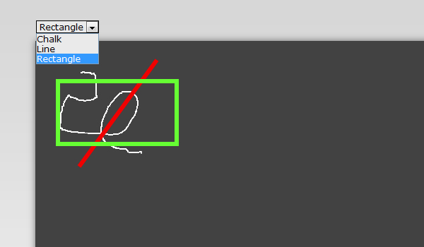
Шаг 1 Что мы делаем
Ниже изображение того, что мы будем делать. Когда мы полностью закончим, ваши могут выглядеть немного иначе, в зависимости от типа стилей, которые вы хотите использовать, и т. Д.
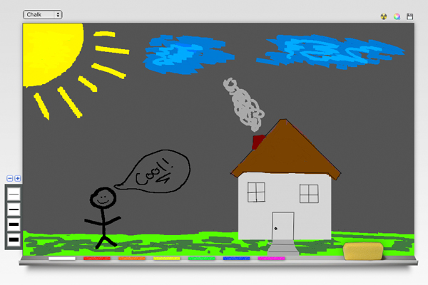
Как видите, я ужасный ящик, но, возможно, после того, как вы закончили создавать свою классную доску, вы можете создать потрясающий шедевр! Кроме того, мы строим доску, а не рисунок!
Шаг 2 Что вам нужно
Для этого урока вам понадобится базовое понимание HTML и JavaScript.
- Photoshop или другой графический редактор
- Редактор кода на ваш выбор
- Базовые знания HTML и JavaScript
- <canvas> поддерживаемый браузер (Chrome, Firefox, Opera, Safari)
Я также буду использовать бесплатный пакет Fugue Icon Pack, который можно скачать здесь: http://p.yusukekamiyamane.com/
Кроме того, мы будем использовать следующие сценарии для достижения окончательного результата.
- Библиотека jQuery 1.4.2
- jQuery Tipsy Подсказки
- Base64 и библиотека Canvas2Image
Шаг 3 Начало работы
Без дальнейших церемоний, давайте сразу начнем!
HTML-разметка
Начните с открытия приложения для кодирования и создайте обычный HTML-документ. Скопируйте и вставьте код ниже. Это базовая структура нашего приложения для рисования. Сохраните документ в новую папку, помеченную как холст (или все, что вы предпочитаете). Теперь на том же уровне, что и ваш HTML-файл, создайте три новые папки.
- JS
- CSS
- Картинки
|
01 02 03 04 05 06 07 08 09 10 11 12 13 14 15 16 17 18 19 20 21 22 23 24 25 26 |
<!DOCTYPE html PUBLIC “-//W3C//DTD XHTML 1.0 Transitional//EN” “http://www.w3.org/TR/xhtml1/DTD/xhtml1-transitional.dtd”> <html xmlns=”http://www.w3.org/1999/xhtml”> <head> <meta http-equiv=”Content-Type” content=”text/html; charset=UTF-8″ /> <!– External CSS Document(s) –> <link rel=”stylesheet” type=”text/css” href=”css/styles.css” /> <title>Online Drawing Application | <!– Eternal JavaScript Document(s) –> <script type=”text/javascript” src=”js/canvas.js”></script> </head> <body> <!– Wrapper Begins –> <div id=”wrapper”> <div id=”blackboardPlaceholder”> </div> </div> </body> </html> |
Это основная разметка нашей страницы. Прежде чем мы начнем писать реальный код, давайте немного его раскроем. Я не буду показывать вам, как сделать дизайн в Photoshop, но вы можете скачать изображения здесь. Обязательно скопируйте все изображения в папку с изображениями, которую вы только что создали.
Разметка CSS
Создайте новую таблицу стилей с именем “styles.css” и сохраните ее в папке “css”. Скопируйте и вставьте следующий базовый код CSS в таблицу стилей.
|
01 02 03 04 05 06 07 08 09 10 11 12 13 14 15 16 17 18 19 20 21 22 23 24 25 26 27 |
@charset “UTF-8”; /* CSS Document */ * { margin:0; body { background:url(../images/bg.gif) repeat-x #f8f8f8; color:#d7d7d7; font-family:”Belle”,”Comic Sans MS”, cursive; font-size:25px; line-height:27px;} #wrapper { position:relative; width:960px; margin:0 auto; padding-top:75px;} <!– Blackboard –> #blackboardPlaceholder { background:url(../images/blackboard.png) no-repeat; width:924px; height:599px; margin:0 auto; padding:14px 0 75px 14px; cursor:crosshair; } |
Шаг 4 Холст тег
Мы собираемся вставить тег canvas прямо в blackboardPlaceholder. Поместите приведенный ниже код внутри идентификатора blackboardPlaceholder.
|
1 2 3 4 5 |
<!– Canvas Begins –> <canvas id=”drawingCanvas” height=”532″ width=”897″> <p class=”noscript”>We’re sorry, this web application is currently not supported with your browser. </canvas> <!– Canvas Ends –> |
Это точная ширина и высота создаваемого нами холста, поэтому нет необходимости его менять. Кроме того, как я уже упоминал выше, все, что находится между тегами canvas, будет отображаться, только если JavaScript отключен или браузер не поддерживает canvas.
Далее, давайте немного стилизовать ID. В вашем файле styles.css добавьте:
|
1 2 3 4 5 6 7 8 |
#drawingCanvas { position:absolute; border:none; color:#FFF; overflow:hidden; background-color:transparent; } #tempCanvas { position: absolute; |
Я скоро объясню идентификатор #tempCanvas, когда мы начнем писать JavaScript.
Шаг 5 Реализация JavaScript
Давайте теперь сделаем так, чтобы наш холст работал так, как должен. Начните с создания нового файла JS и назовите его «canvas». Сохраните этот файл в папке «JS».
Далее мы добавим функцию, чтобы определить, есть ли тег HTML в документе HTML, используя функции addEventListener и onLoad. Вставьте это прямо под переменной, которую мы создали.
|
1 2 3 |
// Check for the canvas tag onload. if(window.addEventListener) { window.addEventListener(‘load’, function () { |
Теперь давайте добавим переменные по умолчанию и некоторые сообщения об ошибках – если что-то пойдет не так
|
01 02 03 04 05 06 07 08 09 10 11 12 13 14 15 16 17 18 19 20 21 22 23 24 25 26 27 28 29 30 31 32 33 34 35 36 37 38 39 |
var canvas, canvaso, contexto; // Default tool. var tool; var tool_default = ‘chalk’; function init () { canvaso = document.getElementById(‘drawingCanvas’); if (!canvaso) { alert(‘Error! The canvas element was not found!’); return; } if (!canvaso.getContext) { alert(‘Error! No canvas.getContext!’); return; } // Create 2d canvas. contexto = canvaso.getContext(‘2d’); if (!contexto) { alert(‘Error! Failed to getContext!’); return; } // Build the temporary canvas. var container = canvaso.parentNode; canvas = document.createElement(‘canvas’); if (!canvas) { alert(‘Error! Cannot create a new canvas element!’); return; } canvas.id = ‘tempCanvas’; canvas.width = canvaso.width; canvas.height = canvaso.height; container.appendChild(canvas); context = canvas.getContext(‘2d’); context.strokeStyle = “#FFFFFF”;// Default line color. context.lineWidth = 1.0;// Default stroke weight. // Fill transparent canvas with dark grey (So we can use the color to erase). context.fillStyle = “#424242”; context.fillRect(0,0,897,532);//Top, Left, Width, Height of canvas. |
Мы создали несколько новых переменных и методов, которые будут использоваться позже.
Context.strokeStyle – это цвет нашего штриха. Мы сделаем значение по умолчанию «#FFFFFF», которое является шестнадцатеричным значением для белого. Далее идет context.lineWidth. Это штрих нашей линии. Мы оставим значение по умолчанию ‘1.0’. Теперь мы создадим серый прямоугольник для использования позже, когда мы добавим возможность сохранять наше изображение. Мы закрасим прямоугольник серым цветом или ‘# 424242’ и сделаем его точным размером нашего холста.
Продолжая, давайте создадим наше выпадающее меню, где мы можем выбирать между мелом, прямоугольником или линией.
|
01 02 03 04 05 06 07 08 09 10 11 12 13 14 15 16 17 18 19 20 21 22 23 24 25 26 27 28 29 30 31 32 33 34 35 36 37 38 39 40 41 42 43 44 45 46 47 48 49 50 51 52 53 54 55 56 57 58 59 60 61 62 63 64 65 66 67 68 |
// Create a select field with our tools. var tool_select = document.getElementById(‘selector’); if (!tool_select) { alert(‘Error! Failed to get the select element!’); return; } tool_select.addEventListener(‘change’, ev_tool_change, false); // Activate the default tool (chalk). if (tools[tool_default]) { tool = new tools[tool_default](); tool_select.value = tool_default; } // Event Listeners. canvas.addEventListener(‘mousedown’, ev_canvas, false); canvas.addEventListener(‘mousemove’, ev_canvas, false); canvas.addEventListener(‘mouseup’, ev_canvas, false); } // Get the mouse position. function ev_canvas (ev) { if (ev.layerX || ev.layerX == 0) { // Firefox ev._x = ev.layerX; ev._y = ev.layerY; } else if (ev.offsetX || ev.offsetX == 0) { // Opera ev._x = ev.offsetX; ev._y = ev.offsetY; } // Get the tool’s event handler. var func = tool[ev.type]; if (func) { func(ev); } } function ev_tool_change (ev) { if (tools[this.value]) { tool = new tools[this.value](); } } // Create the temporary canvas on top of the canvas, which is cleared each time the user draws. function img_update () { contexto.drawImage(canvas, 0, 0); context.clearRect(0, 0, canvas.width, canvas.height); } var tools = {}; // Chalk tool. tools.chalk = function () { var tool = this; this.started = false; // Begin drawing with the chalk tool. this.mousedown = function (ev) { context.beginPath(); context.moveTo(ev._x, ev._y); tool.started = true; }; this.mousemove = function (ev) { if (tool.started) { context.lineTo(ev._x, ev._y); context.stroke(); } }; this.mouseup = function (ev) { if (tool.started) { tool.mousemove(ev); tool.started = false; img_update(); } }; }; |
Мы только что сделали функцию рисования для мела! Очевидно, наш холст все еще не будет работать на этом этапе, но мы почти у цели!
Давайте сделаем наш инструмент прямоугольник сейчас.
|
01 02 03 04 05 06 07 08 09 10 11 12 13 14 15 16 17 18 19 20 21 22 23 24 25 26 27 28 29 30 31 32 33 34 |
// The rectangle tool. tools.rect = function () { var tool = this; this.started = false; this.mousedown = function (ev) { tool.started = true; tool.x0 = ev._x; tool.y0 = ev._y; }; this.mousemove = function (ev) { if (!tool.started) { return; } // This creates a rectangle on the canvas. var x = Math.min(ev._x, tool.x0), y = Math.min(ev._y, tool.y0), w = Math.abs(ev._x – tool.x0), h = Math.abs(ev._y – tool.y0); context.clearRect(0, 0, canvas.width, canvas.height);// Clears the rectangle onload. if (!w || !h) { return; } context.strokeRect(x, y, w, h); }; // Now when you select the rectangle tool, you can draw rectangles. this.mouseup = function (ev) { if (tool.started) { tool.mousemove(ev); tool.started = false; img_update(); } }; }; |
А теперь для инструмента линии.
|
01 02 03 04 05 06 07 08 09 10 11 12 13 14 15 16 17 18 19 20 21 22 23 24 25 26 27 28 29 30 |
// The line tool. tools.line = function () { var tool = this; this.started = false; this.mousedown = function (ev) { tool.started = true; tool.x0 = ev._x; tool.y0 = ev._y; }; this.mousemove = function (ev) { if (!tool.started) { return; } context.clearRect(0, 0, canvas.width, canvas.height); // Begin the line. context.beginPath(); context.moveTo(tool.x0, tool.y0); context.lineTo(ev._x, ev._y); context.stroke(); context.closePath(); }; // Now you can draw lines when the line tool is seletcted. this.mouseup = function (ev) { if (tool.started) { tool.mousemove(ev); tool.started = false; img_update(); } }; }; |
И это почти завершает наш JavaScript! Теперь давайте закроем функцию и переменные, которые мы создали некоторое время назад, заканчивая этим:
Шаг 6 Вставка выбора инструмента
Вернемся к нашей HTML-странице. Теперь мы создадим выбор инструмента, используя основной HTML-тег выпадающего списка.
Прямо под началом тега ‘blackboardPlaceholder’ и прямо перед нашим тегом canvas добавьте приведенный ниже код, чтобы создать выпадающий список инструментов.
|
1 2 3 4 5 6 7 |
<p><!– Tool Selector –> <select name=”selector” id=”selector”> <option value=”chalk”>Chalk</option> <option value=”line”>Line</option> <option value=”rect”>Rectangle</option> </select> </p> |
Вот и все! Теперь у нас есть выпадающая форма, давайте добавим немного стиля.
|
01 02 03 04 05 06 07 08 09 10 11 |
.noscript { padding:50px 30px 0 40px; #selector { position:absolute; z-index:99999; margin-top:-30px; } select { font-family:Verdana, Geneva, sans-serif; font-size:12px; background-color:#EAEAEA; } |
.Noscript – это стиль текста между тегами canvas, который мы никогда не добавляли выше.
Шаг 7 Изменение цвета
Просто чтобы сообщить вам, это мелки. Я чувствовал, что из-за моих дизайнерских навыков, я должен был сообщить вам, что они были, потому что многие люди рассказывали мне, как они не выглядят отдаленно близко к мелку
На самом деле довольно легко изменить цвет в HTML. Все, что вам нужно сделать, это использовать функцию onclick. Ссылки, изображения, текст, классы и т. Д. Функция, которую мы используем для изменения цвета, приведена ниже.
|
1 |
onclick=”context.strokeStyle = ‘#ff00d2’;” |
Чтобы изменить цвет, просто измените шестнадцатеричный код цвета между скобками. # FF00D2, использованный выше, изменит цвет обводки на розовый.
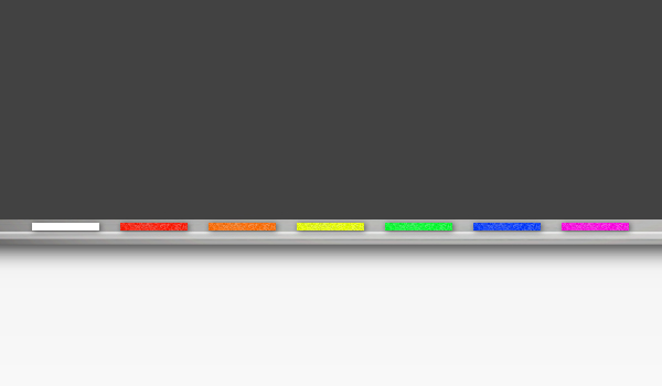
Теперь давайте добавим разметку HTML для кусочков мела.
|
01 02 03 04 05 06 07 08 09 10 11 12 13 14 15 16 17 18 19 20 21 22 |
<!– Chalk Pieces –> <div id=”whiteChalk_button”> <img src=”images/white.png” width=”71″ height=”17″ onclick=”context.strokeStyle = ‘#FFFFFF’;” </div> <div id=”redChalk_button”> <img src=”images/red.png” width=”71″ height=”17″ onclick=”context.strokeStyle = ‘#F00000’;” </div> <div id=”orangeChalk_button”> <img src=”images/orange.png” width=”71″ height=”17″ onclick=”context.strokeStyle = ‘#ff9600’;” </div> <div id=”yellowChalk_button”> <img src=”images/yellow.png” width=”71″ height=”17″ onclick=”context.strokeStyle = ‘#fff600’;” </div> <div id=”greenChalk_button”> <img src=”images/green.png” width=”71″ height=”17″ onclick=”context.strokeStyle = ‘#48ff00’;” </div> <div id=”blueChalk_button”> <img src=”images/blue.png” width=”71″ height=”17″ onclick=”context.strokeStyle = ‘#001eff’;” </div> <div id=”pinkChalk_button”> <img src=”images/pink.png” width=”71″ height=”17″ onclick=”context.strokeStyle = ‘#ff00d2’;” </div> |
Добавьте приведенный выше код прямо под тегом </ canvas>.
Ваш HTML-код должен выглядеть следующим образом.
|
01 02 03 04 05 06 07 08 09 10 11 12 13 14 15 16 17 18 19 20 21 22 23 24 25 26 27 28 29 30 31 32 33 34 35 36 37 38 39 40 41 |
<!DOCTYPE html PUBLIC “-//W3C//DTD XHTML 1.0 Transitional//EN” “http://www.w3.org/TR/xhtml1/DTD/xhtml1-transitional.dtd”> <html xmlns=”http://www.w3.org/1999/xhtml”> <head> <meta http-equiv=”Content-Type” content=”text/html; charset=UTF-8″ /> <!– External CSS Document(s) –> <link rel=”stylesheet” type=”text/css” href=”css/styles.css” /> <title>Online Drawing Application | <!– Eternal JavaScript Document(s) –> <script type=”text/javascript” src=”js/canvas.js”></script> </head> <body> <!– Wrapper Begins –> <div id=”wrapper”> <div id=”blackboardPlaceholder”> <p><!– Tool Selector –><select name=”selector” id=”selector”><option value=”chalk”>Chalk</option><option value=”line”>Line</option><option value=”rect”>Rectangle</option></select></p> <!– Canvas Begins –><canvas id=”drawingCanvas” height=”532″ width=”897″> <p class=”noscript”>We’re sorry, this web application is currently not supported with your browser. <!– Chalk Pieces –><div id=”whiteChalk_button”><img src=”images/white.png” width=”71″ height=”17″ onclick=”context.strokeStyle = ‘#FFFFFF’;” <div id=”redChalk_button”><img src=”images/red.png” width=”71″ height=”17″ onclick=”context.strokeStyle = ‘#F00000’;” </div> <div id=”orangeChalk_button”><img src=”images/orange.png” width=”71″ height=”17″ onclick=”context.strokeStyle = ‘#ff9600’;” </div> <div id=”yellowChalk_button”><img src=”images/yellow.png” width=”71″ height=”17″ onclick=”context.strokeStyle = ‘#fff600’;” <div id=”greenChalk_button”> <img src=”images/green.png” width=”71″ height=”17″ onclick=”context.strokeStyle = ‘#48ff00’;” <div id=”blueChalk_button”><img src=”images/blue.png” width=”71″ height=”17″ onclick=”context.strokeStyle = ‘#001eff’;” <div id=”pinkChalk_button”><img src=”images/pink.png” width=”71″ height=”17″ onclick=”context.strokeStyle = ‘#ff00d2’;” </div> </div> </body> </html> |
Шаг 8 Добавление ластика
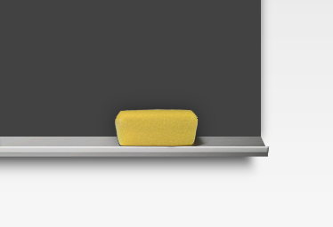
Ластик – это просто изображение, которое имеет тот же цвет обводки, что и прямоугольник, который мы создали в JavaScript, «# 424242». Скопируйте и вставьте HTML-код под мелом, который мы только что создали.
|
1 2 |
<!– Eraser –> <div id=”eraser” onclick=”context.strokeStyle = ‘#424242′; context.lineWidth = ’22’;”></div> |
Шаг 9 Стилизация мела и ластика
Теперь давайте добавим немного стилей к частям мела и ластику, прежде чем мы пойдем дальше. Добавьте следующее в ваш файл styles.css.
|
01 02 03 04 05 06 07 08 09 10 11 12 13 14 15 16 17 |
#redChalk_button { cursor:pointer; #greenChalk_button { cursor:pointer; #blueChalk_button { cursor:pointer; #yellowChalk_button { cursor:pointer; #orangeChalk_button { cursor:pointer; #pinkChalk_button { cursor:pointer; #whiteChalk_button { cursor:pointer; #eraser { position:absolute; background:url(../images/eraser.png) no-repeat; left: 737px; top: 568px; width: 139px; height: 67px; z-index:99999; cursor:pointer; } |
Шаг 10 Изменение веса удара
Изменить обводку так же просто, как изменить цвет в HTML. Все, что вам нужно сделать, это использовать функцию «onclick»:
|
1 |
onclick=”context.lineWidth = ‘1.0’;” |
«1.0» – наименьший допустимый ход. Вы можете увеличить ход, сколько хотите.
Теперь давайте добавим некоторые штриховые функции в наш HTML. Скопируйте и вставьте приведенный ниже код в ваш HTML-документ. Вам нужно будет поместить это вне ‘blackboardPlaceholder’, сразу же после закрывающего тега div (до окончания оболочки).
|
01 02 03 04 05 06 07 08 09 10 11 |
<!– Toggle Stroke Weight –> <img src=”images/toggle.png” width=”16″ height=”16″ id=”stroke-subtract” title=”Decrease Stroke” onclick=”context.lineWidth–;” <img src=”images/toggle-expand.png” width=”16″ height=”16″ id=”stroke-add” title=”Increase Stroke” onclick=”context.lineWidth++;” <!– Stroke Weight Panel –> <div id=”strokeWeight”> <img src=”images/stroke1.png” alt=”1.0″ class=”stroke” width=”30″ height=”32″ onclick=”context.lineWidth = ‘1.0’;” <img src=”images/stroke2.png” alt=”6.0″ class=”stroke” width=”30″ height=”32″ onclick=”context.lineWidth = ‘6.0’;” <img src=”images/stroke3.png” alt=”9.0″ class=”stroke” width=”30″ height=”32″ onclick=”context.lineWidth = ‘9.0’;” <img src=”images/stroke4.png” alt=”13.0″ class=”stroke” width=”30″ height=”32″ onclick=”context.lineWidth = ‘13.0’;” </div> |
Теперь немного CSS:
|
01 02 03 04 05 06 07 08 09 10 11 12 13 14 15 16 17 18 19 20 21 22 23 24 25 |
#stroke-subtract { position:absolute; top:436px; left:-13px; z-index:999999; cursor:pointer; } #stroke-add { position:absolute; top:436px; left:5px; z-index:999999; cursor:pointer; } #strokeWeight { background:url(../images/stroke-style.png) no-repeat; width:43px; height:153px; position:absolute; top:456px; left:-18px; z-index:1; padding:8px 0 0 7px; } .stroke { cursor:pointer; |
Шаг 11 Функция сохранения
Это, пожалуй, самый сложный раздел нашего урока. Мы будем использовать функцию JavaScript image / data для сохранения нашего изображения. Но сначала нам нужна библиотека изображений. Мы будем использовать Canvas2Image и библиотеку Base64, созданные Джейкобом Сейделином на nihilogic.dk .
Если вы этого еще не сделали, вы можете загрузить эти файлы здесь и поместить их в папку «js».
Нам нужно изменить файл canvas.js. Добавьте следующее в конец вашего файла.
|
01 02 03 04 05 06 07 08 09 10 11 12 13 14 15 16 17 18 19 20 21 22 23 24 25 26 27 28 29 30 31 32 33 34 35 36 37 38 39 40 41 42 43 44 45 46 47 48 49 50 |
window.onload = function() { var bMouseIsDown = false; var oCanvas = document.getElementById(“drawingCanvas”); var oCtx = oCanvas.getContext(“2d”); var iWidth = oCanvas.width; var iHeight = oCanvas.height; function showDownloadText() { document.getElementById(“textdownload”).style.display = “block”; } function hideDownloadText() { document.getElementById(“textdownload”).style.display = “none”; } function convertCanvas(strType) { if (strType == “PNG”) var oImg = Canvas2Image.saveAsPNG(oCanvas, true); if (strType == “BMP”) var oImg = Canvas2Image.saveAsBMP(oCanvas, true); if (strType == “JPEG”) var oImg = Canvas2Image.saveAsJPEG(oCanvas, true); if (!oImg) { alert(“Sorry, this browser is not capable of saving.” + strType + ” files!”); return false; } oImg.id = “canvasimage”; oImg.style.border = oCanvas.style.border; oCanvas.parentNode.replaceChild(oImg, oCanvas); howDownloadText(); } function saveCanvas(pCanvas, strType) { var bRes = false; if (strType == “PNG”) bRes = Canvas2Image.saveAsPNG(oCanvas); if (strType == “BMP”) bRes = Canvas2Image.saveAsBMP(oCanvas); if (strType == “JPEG”) bRes = Canvas2Image.saveAsJPEG(oCanvas); if (!bRes) { alert(“Sorry, this browser is not capable of saving ” + strType + ” files!”); return false; } } document.getElementById(“convertpngbtn”).onclick = function() { convertCanvas(“PNG”); } document.getElementById(“resetbtn”).onclick = function() { var oImg = document.getElementById(“canvasimage”); oImg.parentNode.replaceChild(oCanvas, oImg); hideDownloadText(); }} |
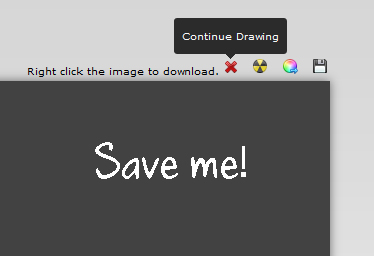
По сути, когда вы нажимаете кнопку «Сохранить», она преобразует ваш холст в PNG, и оттуда вы сможете щелкнуть правой кнопкой мыши и загрузить изображение. Довольно аккуратно, верно !?
Теперь давайте добавим HTML:
|
01 02 03 04 05 06 07 08 09 10 |
<!– Save Image –> <div id=”saveWrapper”> <div id=”save”> <img src=”images/save.png” alt=”Save Image” width=”16″ height=”16″ id=”convertpngbtn” title=”Save Image” /> </div> <div id=”textdownload”> Right click the image to download. <img src=”images/cross.png” alt=”Cancel” width=”16″ height=”16″ id=”resetbtn” title=”Continue Drawing” /> </div> </div> |
Добавьте приведенный выше код сразу после оболочки; это создаст кнопки сохранения и очистки. Теперь мы добавим CSS, чтобы немного его стилизовать.
|
01 02 03 04 05 06 07 08 09 10 11 12 13 14 15 16 17 18 19 20 21 22 |
#saveWrapper { position:absolute; #convertpngbtn { float:right; margin-right:40px; margin-top:-10px; position:relative; z-index:9999; cursor:pointer; overflow:hidden; } #textdownload { display:none; position:absolute; font-family:Verdana, Geneva, sans-serif; color:#000; font-size:10px; float:right; margin-top:-10px; right:91px; width:250px; overflow:hidden; } |
Просто добавьте этот код в таблицу стилей styles.css.
Шаг 12 Таблица расширенных цветов
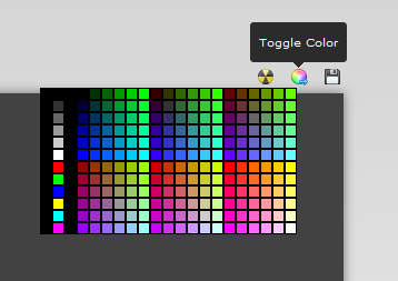
Чтобы добавить больше гибкости, мы должны создать таблицу цветов, аналогичную той, которая используется в Dreamweaver CS4.
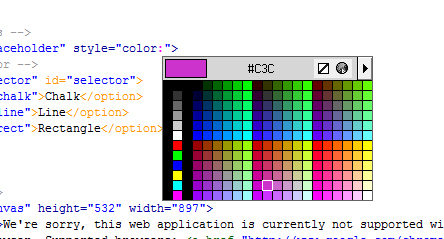
Поэтому я решил, что на самом деле это будет довольно легко. Я хотел бы сохранить вышеприведенную таблицу цветов, а затем использовать ее в качестве фонового изображения идентификатора div, а затем внутри, иметь отдельный класс div для каждого цвета с той же функцией onclick, которую мы использовали выше. Вскоре я понял, что это не лучшее решение, так как это создаст беспорядок в HTML и потребует вечной загрузки каждого div. Поэтому вместо этого я придумала новое решение, которое состоит исключительно из JavaScript. Я бы динамически создавал каждый div в моем файле JavaScript и вставлял код цвета для каждого «цветового блока» в массив. Поэтому, прежде чем я объясню, мы сделаем именно это. Откройте ваш файл JavaScript, над которым мы работали, и в самом верху файла прямо под контекстной переменной создайте новую переменную с именем «colorPalette». Тогда мы начнем массив. Каждая новая строка цветов отделялась одной строкой пробела в JavaScript. Всего существует двенадцать столбцов, поэтому в нашем массиве будет всего двенадцать разделов.
Вот JavaScript:
|
01 02 03 04 05 06 07 08 09 10 11 12 13 14 15 16 17 18 19 20 21 22 23 24 25 26 27 |
var colorPalette = [ //Begin array of color table hex color codes. “#000000″,”#000000″,”#000000″,”#000000″,”#003300″,”#006600″,”#009900″,”#00CC00″,”#00FF00″,”#330000″,”#333300″,”#336600″,”#339900″,”#33CC00″,”#33FF00″,”#660000″,”#663300″,”#666600″,”#669900″,”#66CC00″,”#66FF00”, “#000000″,”#333333″,”#000000″,”#000033″,”#003333″,”#006633″,”#009933″,”#00CC33″,”#00FF33″,”#330033″,”#333333″,”#336633″,”#339933″,”#33CC33″,”#33FF33″,”#660033″,”#663333″,”#666633″,”#669933″,”#66CC33″,”#66FF33”, “#000000″,”#666666″,”#000000″,”#000066″,”#003366″,”#006666″,”#009966″,”#00CC66″,”#00FF66″,”#330066″,”#333366″,”#336666″,”#339966″,”#33CC66″,”#33FF66″,”#660066″,”#663366″,”#666666″,”#669966″,”#66CC66″,”#66FF66”, “#000000″,”#999999″,”#000000″,”#000099″,”#003399″,”#006699″,”#009999″,”#00CC99″,”#00FF99″,”#330099″,”#333399″,”#336699″,”#339999″,”#33CC99″,”#33FF99″,”#660099″,”#663399″,”#666699″,”#669999″,”#66CC99″,”#66FF99”, “#000000″,”#CCCCCC”,”#000000″,”#0000CC”,”#0033CC”,”#0066CC”,”#0099CC”,”#00CCCC”,”#00FFCC”,”#3300CC”,”#3333CC”,”#3366CC”,”#3399CC”,”#33CCCC”,”#33FFCC”,”#6600CC”,”#6633CC”,”#6666CC”,”#6699CC”,”#66CCCC”,”#66FFCC”, “#000000″,”#FFFFFF”,”#000000″,”#0000FF”,”#0033FF”,”#0066FF”,”#0099FF”,”#00CCFF”,”#00FFFF”,”#3300FF”,”#3333FF”,”#3366FF”,”#3399FF”,”#33CCFF”,”#33FFFF”,”#6600FF”,”#6633FF”,”#6666FF”,”#6699FF”,”#66CCFF”,”#66FFFF”, “#000000″,”#FF0000″,”#000000″,”#990000″,”#993300″,”#996600″,”#999900″,”#99CC00″,”#99FF00″,”#CC0000″,”#CC3300″,”#CC6600″,”#CC9900″,”#CCCC00″,”#CCFF00″,”#FF0000″,”#FF3300″,”#FF6600″,”#FF9900″,”#FFCC00″,”#FFFF00”, “#000000″,”#00FF00″,”#000000″,”#990033″,”#993333″,”#996633″,”#999933″,”#99CC33″,”#99FF33″,”#CC0033″,”#CC3333″,”#CC6633″,”#CC9933″,”#CCCC33″,”#CCFF33″,”#FF0033″,”#FF3333″,”#FF6633″,”#FF9933″,”#FFCC33″,”#FFFF33”, “#000000″,”#0000FF”,”#000000″,”#990066″,”#993366″,”#996666″,”#999966″,”#99CC66″,”#99FF66″,”#CC0066″,”#CC3366″,”#CC6666″,”#CC9966″,”#CCCC66″,”#CCFF66″,”#FF0066″,”#FF3366″,”#FF6666″,”#FF9966″,”#FFCC66″,”#FFFF66″, “#000000″,”#FFFF00″,”#000000″,”#990099″,”#993399″,”#996699″,”#999999″,”#99CC99″,”#99FF99″,”#CC0099″,”#CC3399″,”#CC6699″,”#CC9999″,”#CCCC99″,”#CCFF99″,”#FF0099″,”#FF3399″,”#FF6699″,”#FF9999″,”#FFCC99″,”#FFFF99”, “#000000″,”#00FFFF”,”#000000″,”#9900CC”,”#9933CC”,”#9966CC”,”#9999CC”,”#99CCCC”,”#99FFCC”,”#CC00CC”,”#CC33CC”,”#CC66CC”,”#CC99CC”,”#CCCCCC”,”#CCFFCC”,”#FF00CC”,”#FF33CC”,”#FF66CC”,”#FF99CC”,”#FFCCCC”,”#FFFFCC”, “#000000″,”#FF00FF”,”#000000″,”#9900FF”,”#9933FF”,”#9966FF”,”#9999FF”,”#99CCFF”,”#99FFFF”,”#CC00FF”,”#CC33FF”,”#CC66FF”,”#CC99FF”,”#CCCCFF”,”#CCFFFF”,”#FF00FF”,”#FF33FF”,”#FF66FF”,”#FF99FF”,”#FFCCFF”,”#FFFFFF” ]; |
И это каждый цвет в нашей таблице цветов. Теперь давайте добавим JavaScript, чтобы он работал.
|
01 02 03 04 05 06 07 08 09 10 11 12 13 14 15 16 17 18 19 20 21 22 23 24 25 26 27 |
$(document).ready(function() { // Handles showing/hiding the color table $(“#colorTable”).hide(); $(“#color”).click(function() { $(“#colorTable”).show(); }); $(document).click(function() { $(“#colorTable”).hide(); }); $(“#color”).click(function(event) { event.stopPropagation(); }); }); function LoadColorTable() { // Populate the color picker table with colors specified in the ‘colorPalette’ array for (i = 0; i < colorPalette.length; i++) { var colorDiv = document.createElement(“div”); colorDiv.className = “color”; colorDiv.id = “colorSwatch” + i; colorDiv.style.backgroundColor = colorPalette[i]; colorDiv.setAttribute(“onclick”, “SetColor(id);”); document.getElementById(“colorTable”).appendChild(colorDiv); }; } function SetColor(id) { // Set the color of the drawing tool when a color swatch is clicked context.strokeStyle = document.getElementById(id).style.backgroundColor; } |
Итак, приведенный выше код, мы начнем с добавления некоторых функций для отображения или скрытия идентификатора colorTable в нашем HTML (к которому мы вскоре перейдем). Это просто базовый jquery, потому что когда вы нажимаете colorTable или в любом месте за пределами colorTable, он будет скрывать идентификатор. Теперь мы загрузим таблицу цветов. Сделайте это, мы заполним его всеми кодами цветов, которые мы добавили в массив ‘colorPalette’. И наконец, чтобы все заработало, мы установим цвет инструмента рисования при нажатии на образец цвета. Чтобы сделать это, мы просто сделаем каждый цвет классом «color», а затем используем массив, чтобы сделать каждое шестнадцатеричное значение цвета фоном. И наконец, используйте функцию, чтобы при нажатии цвета context.strokeStyle совпадал с фоновым изображением.
А для разметки HTML вы добавите следующий код сразу после запуска оболочки в вашем HTML.
|
1 2 3 4 5 6 |
<!– Color Table (controlled in JavaScript) –> <div id=”colorTable”></div> <!– Toggle Color Button –> <div id=”color” title=”Toggle Color”> <img src=”images/color-arrow.png” alt=”Toggle Color” width=”16″ height=”16″ /> </div> |
А теперь давайте добавим стиль в нашу таблицу цветов.
|
01 02 03 04 05 06 07 08 09 10 11 12 13 14 15 16 17 18 19 20 |
#colorTable { width:231px; height:132px; position:absolute; margin-top:8px; z-index:999999; right:80px; background-color: #000000; display:none; cursor:pointer; } .color { position:relative; height:7px; width:7px; float:left; padding:1px; margin:1px; } .color:hover{ border:solid 1px #FFF; |
Добавьте это куда угодно в свой файл styles.css, который вы создали некоторое время назад.
И вот оно! Теперь у нас есть более 200 различных цветов, которые мы можем выбрать!
Шаг 13 Использование функции перезагрузки для очистки холста
Теперь мы создадим простую кнопку для очистки холста. Самый простой способ сделать это – просто обновить страницу. Итак, мы собираемся использовать функцию, я уверен, что вы все знакомы. Если нет, то приведенный ниже код просто обновит страницу с помощью JavaScript.
|
1 |
<a href=”javascript:location.reload(true)”>Clear</a> |
Вот и все. Итак, теперь давайте добавим это в наш HTML. Мы будем использовать изображение в вашей папке ‘images’, которое выглядит как радиоактивный символ. Я не уверен, почему я использовал радиоактивный символ для этого, но я не мог найти никакой другой значок в пакете значков для использования, поэтому этого будет достаточно.
Добавьте следующее изображение к HTML ниже. Поскольку он имеет абсолютную позицию, на самом деле не имеет значения, где вы его разместите, если размещаете его вне «blackboardPlaceholder» и внутри «обертки». Поэтому, чтобы код выглядел «по порядку», мы собираемся разместить следующий код сразу после нашего идентификатора «color».
|
1 2 3 4 5 6 |
<!– Clear Canvas Button –> <div id=”nuke” title=”Clear Canvas”> <a href=”javascript:location.reload(true)”> <img src=”images/burn.png” alt=”Clear Canvas” width=”16″ height=”16″ /> </a> </div> |
И, конечно же, немного CSS:
|
1 |
#nuke { position:absolute; |
И там у вас есть это. Приятно выглядящая кнопка «Очистить».
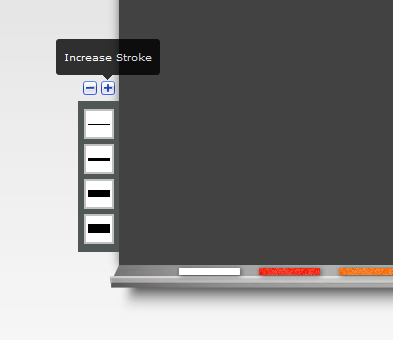
Шаг 14 Добавление дополнительной функции в меню обводки
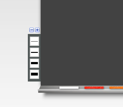
После того как я заполнил это приложение для рисования, я все еще чувствовал, что вес ударов, которые вы смогли выбрать, все еще был немного низким. Так что я решил сделать для этого новую небольшую функцию. Я не буду удалять меню штрихов, которое у нас уже есть, я просто добавлю к нему немного. Моя идея состояла в том, чтобы иметь кнопку плюс и минус. Кнопка «плюс» увеличивает вес хода на единицу, а кнопка «минус», очевидно, уменьшает ход на единицу.
Поэтому, чтобы сделать это, мы найдем несколько хороших кнопок «плюс» и «минус» в нашем наборе иконок. Затем мы напишем HTML-код над идентификатором «storkeWeight».
|
1 2 3 |
<!– Toggle Stroke Weight –> <img src=”images/toggle.png” width=”16″ height=”16″ id=”stroke-subtract” title=”Decrease Stroke” onclick=”context.lineWidth–;” <img src=”images/toggle-expand.png” width=”16″ height=”16″ id=”stroke-add” title=”Increase Stroke” onclick=”context.lineWidth++;” |
Функция onclick немного отличается от того, что мы использовали ранее, в основном значения ‘-‘ и ‘++’ просто добавят или вычтут 1 из значения по умолчанию. Значение по умолчанию – 1,0, поэтому при нажатии кнопки «плюс» обводка теперь будет 2,0, что немного больше значения по умолчанию.
А теперь CSS:
|
01 02 03 04 05 06 07 08 09 10 11 12 13 14 |
#stroke-subtract { position:absolute; top:436px; left:-13px; z-index:999999; cursor:pointer; } #stroke-add { position:absolute; top:436px; left:5px; z-index:999999; cursor:pointer; } |
Шаг 15 Добавление подсказок
Чтобы сделать приложение более удобным для пользователя, нам нужно добавить несколько заголовков для всех наших кнопок. К счастью, я уже включил весь код в HTML, вы просто не заметили этого. В основном все наши иконки в коде HTML имеют тег заголовка. Вы все должны знать, что такое теги заголовков, но мы собираемся использовать эти теги для реализации довольно приятного эффекта всплывающей подсказки jQuery, известного как Tipsy. Я использовал Tipsy много раз в других проектах, и это действительно отличный плагин. Вам нужно будет скачать файлы Tipsy здесь . Поместите файл tipsy.css в папку css, файл jquery.tipsy.js в папку js и файл tipsy.gif в папку с изображениями, если его там еще нет.
Вам нужно будет добавить библиотеку jQuery в ваш заголовок. Вот прямая ссылка на последнюю библиотеку jQuery. Вы можете сделать ссылку непосредственно на это или загрузить его в папку «js»:
http://ajax.googleapis.com/ajax/libs/jquery/1.4.2/jquery.min.js
Теперь нам нужно вызвать файл JavaScript для типси. Убедитесь, что когда вы вызываете это в своем заголовке, сценарий jQuery предшествует этому сценарию. Это должно выглядеть так:
|
1 |
<script type=”text/javascript” src=”js/jquery.tipsy.js”></script> |
А затем вызовите файл tipsy.css в своем HTML. Это должно выглядеть следующим образом:
|
1 |
<link rel=”stylesheet” type=”text/css” href=”css/tipsy.css” /> |
А теперь давайте назовем фактически JavaScript. Поместите это в свой заголовок ниже всех внешних источников JavaScript и CSS.
|
1 2 3 4 5 6 7 8 9 |
<script type=’text/javascript’> $(function() { $(‘#nuke’).tipsy({gravity: ‘s’}); $(‘#color’).tipsy({gravity: ‘s’}); $(‘#convertpngbtn’).tipsy({gravity: ‘s’}); $(‘#resetbtn’).tipsy({gravity: ‘s’}); $(‘#stroke-subtract’).tipsy({gravity: ‘s’}); $(‘#stroke-add’).tipsy({gravity: ‘s’}); </script> |
Вам также нужно добавить еще одну вещь в ваш файл styles.css, чтобы немного вспомнить всплывающие подсказки:
|
1 2 3 4 5 6 7 8 |
.tooltip{ position: absolute; top: 0; left: 0; z-index: 3; display: none; background-color:#F00; } |
Завершение
И это как раз оборачивает это! Поздравляю. Пожалуйста, дайте мне знать, если у вас есть какие-либо вопросы или мысли о том, как улучшить это приложение. Спасибо за прочтение!
This tutorial will help you create a paint program with basic tools like lines, circles, brushes and color choices. These tools are quite similar so after getting a lot of help with the first one, you will be able to do the others with less and less help — a nice way to ease into Delphi programming.
Starting the Program[]
Create a folder named «Paint» for this project, possibly in the «My Documents» folder on your computer. Of course you can name it anything you like, but I will use the name «Paint» in this article.
Run Delphi and, in the file menu, choose «New Application»(Delphi 2010: File->New->VCL Froms Application — Delphi).
This should create two windows named «Form1» and «Unit1». You can switch between them quickly by pressing the F12 key.
Click on the unit so it is in front of everything else. Choose File — Save As, name it «main» and direct it into your paint folder.
Then choose File — Save Project As and name it «paint».
Click on the form. Press the F11 key to select the object inspector. Right under its title it should say «Form1» to indicate it is presently inspecting the details of the form. In the list below, find the item «name» and beside it change «Form1» to «MainForm». This will help keep things organized when you have lots of forms (windows and dialogs) in your project.
Exit from Delphi, saving if it asks. Look in your Paint folder. You should find 5 files related to this project: main.pas, main.dfm and several beginning with paint. You will normally begin work on your project by doubleclicking on Paint.dpr — the project file.
The Main Menu[]
On the component bar at the top or right side of Delphi’s main window, you should find a series of tabs labelled «standard, additional, win32 …». Click on «standard». Just below the tabs are icons of various standard components. Hold the mouse pointer over one for a second or two to see a brief description. The first one is described as «mainmenu». Click on the «mainmenu» component, then click anywhere on your form. The mainmenu icon should appear on your form. It doesn’t matter where on the form you place this particular component.
Doubleclick on your mainmenu to open it. Nothing much there so far, except a blank entry which should be selected. Press the F11 key to inspect it. Find the «name» in the object inspector’s list and enter the name «FileMenu». Find the «Caption» and enter «File». Click the x icon at the upper right corner of the mainmenu window to close it.
Your program should run now. Choose «Run» in the «Run» menu. After a moment of compiling, you should see your form appear with its main menu containing only the «File» item. Of course it doesn’t work yet. Click the x button to close it.
Let’s add an Exit item to the file menu. Doubleclick on your mainmenu object, select the blank item hanging under the word «File» and press F11 to edit it. Change the «Caption» to «Exit». The name should automatically change to «Exit1», which is as good as any. When you run your program, you should find that the file menu now has an exit command, but it still doesn’t work. Again you have to click x to close your program.
With your program NOT running, pull down the File menu and choose «Exit». This automatically creates an exit response procedure in your main unit. Here is where you write the code that makes your program work:
procedure TMainform.Exit1Click(Sender: TObject);
begin
  MainForm.Close;
end;
You just have to type MainForm.Close — Delphi has written the routine stuff for you automatically. The response procedure holds the detailed programming for an action like choosing a menu command. When the program is running and someone chooses «Exit», Windows gives control to your Exit1Click procedure and follows the instruction you entered.
Run your program again (choose run in Delphi’s run menu) and you will find that your file-exit command works.
Congratulations on getting one of your program’s commands to actually work!
The Toolbar Panel[]
Our program needs a set of painting tools (pencil, line, brush, etc.) to choose from.
Begin by choosing a panel component to hold all the tool buttons. On the component bar at the top or right side of the mainform, click the panel component in the «standard» tab, then click it onto your form. Drag it wherever you like; you can always move it later. In fact, the purpose of the panel is to allow us to move all the tools as a group more easily. You can get rid of the «Panel1» caption in the middle by using the object inspector to change its caption to a blank. Let’s leave the name as
Adding a SpeedButton[]
Delphi has a number of different buttons that could be used for the toolbar. The speedbutton on the «additional» tab has the advantage of being easy to put an icon on and to indicate when it is selected. The speedbutton looks like a lightning bolt — if you are in doubt hold the cursor over each component until you see its hint. Put a speedbutton on the panel. Use the object inspector to name it «Pencil», and to make the GroupIndex 1 and Enabled True.
We need to draw a picture of a pencil to put on the speedbutton. Delphi has a little icon editor built in. I’m using Delphi 5, so what I’m seeing may not be exactly the same as what you are seeing. In the Tools menu, choose «Image Editor». Pull down its file menu and choose new bitmap image. Make it 64 dots wide and 16 high in 16 colors. Use the pencil tool to make vertical dividing lines splitting the bitmap into 4 equal parts. Choose the magnifying glass and right click (choosing zoom in) a couple of times to make the 64×16 bitmap large enough to work with. Count 16 squares for each part. The first part is the normal appearance of your pencil tool. The third part is the appearance when clicked and the fourth part is what it looks like when held down. Draw them any way you like! You can simply use a different background color for the 3rd part. Erase or cover up the black lines to the right of the 1st and 3rd parts — they are part of the pictures. Save in your folder, using the name Pencil.bmp.
Now you need to tell Delphi that you want to use Pencil.bmp as the glyph for the pencil speedbutton. Click on the speedbutton. Press F11 to bring up the object inspector. Click on the blank to the right of «Glyph», then on the 3 dots that appear there. In the dialog that opens, choose «Load», then find pencil.bmp and doubleclick it. Presto, your button should have your picture on it.
Run your program and see what happens when you click on the pencil button. It should change appearance. If you want to change the picture, open it with the image editor (or any paint program), edit, save, then choose it again in the object inspector.
An Image to Paint on[]
It is possible to paint on the bare form, but adding an image component makes it easy to load and save the image. On the component palette, click the «additional» tab and choose the image component. Place it on your form and adjust to the size you want. It should already be named «Image1».
test
Getting Ready to Draw: a Boolean Variable[]
We need a variable to keep track of whether or not we have started using the pencil. Add the drawingNow variable near the top of your unit window, as shown below: (the first 2 lines are already there; just add the 3rd line)
var
  Mainform: TMainform;
  drawingNow: Boolean;
drawingNow is a Boolean variable. This means it can have only two possible values, either True or False. We want it to be False when the program first runs. To ensure this do the following: Double-clicking on the form away from any components will generate the OnCreate Handler. Another way of doing this goes as follows: click on your form, away from any components. Press F11. Confirm that the object inspector says «mainform» at the top. Click the «Events» tab just below this, and look for the «OnCreate» item in the list below that. Doubleclick in the blank to the right of «OnCreate.» This should create a Procedure FormCreate in your unit. You need to add a line of programming code in this procedure:
procedure TMainform.FormCreate(Sender: TObject);
begin
  drawingNow := False;
end;
Click on Image1 on your form. Press F11 and, under the events tab, doubleclick to the right of «OnMouseDown«. This creates a procedure in the unit. Windows directs control of the program to this procedure when someone clicks on the image. Type the 2 lines between begin and end to tell Windows to move its attention to where the mouse was clicked, and make drawingNow true if the pencil button has been depressed.
procedure TMainform.Image1MouseDown(Sender: TObject;
  Button: TMouseButton; Shift: TShiftState;
  X, Y: Integer);
begin
  Image1.Canvas.MoveTo(x, y);

  if Pencil.Down then
    drawingNow := True;
end;
The Pencil.Down reference is a neat dividend of object oriented programming. We have an object named «Pencil» (the button you made) and it has a property called «Down». The name «Pencil.Down» makes sense and is easy to understand. If you happen to get an error to the effect that there is no such thing as «Pencil.Down», you would naturally check to make sure you did name the button «Pencil» and perhaps check the object inspector to make sure it is a type of object that actually has a «Down» property.
Let’s Draw![]
The next step tells Windows to actually draw something on the image! Select image1 on the form, press F11 and doubleclick to the right of “OnMouseMove”. Add one line of code to the procedure that gets control when the user of your program moves the mouse:
procedure TMainform.Image1MouseMove(Sender: TObject;
   Button: TMouseButton; Shift: TShiftState;
  X, Y: Integer);
begin
  if drawingNow = True then
    Image1.Canvas.LineTo(x, y);
end;
This line of code tells Windows to draw a line from where it was before to the current mouse location (x,y).
The pencil button needs a bit of tweeking. Click on the pencil button, press F11, click the properties tab. Enter a «group index» of 1 and doubleclick to the right of AllowAllUp to make it say “true”. More on this later.
Run your program. You should find that you can write on the image after clicking on the button to turn it on.
The pencil tool should turn off when you release the mouse button. Select image1, press F11, the events tab and doubleclick to the right of “on mouse up”.
procedure TMainform.Image1MouseUp(Sender: TObject;
   Button: TMouseButton; Shift: TShiftState;
  X, Y: Integer);
begin
  drawingNow := False;
end;
Understanding the Code[]
Try to understand everything you typed in the unit, so you can figure out another painting tool on your own. It might help to write in plain English what happens as the user clicks the pencil button, then draws on the image:
- When user clicks the pencil button: Pencil.Down becomes True
- When user clicks on the image:
    - Move the current position to the mouse pointer location
    - If the pencil button is down, make drawingNow true
- When the mouse moves on the image:
    - If we are drawing, then draw a line from the previous position
      to the present mouse position
This kind of plan is called programming pseudocode.
Saving the Painting[]
Doubleclick on the mainmenu component on your mainform. Right click on «Exit» under the file menu and choose Insert (the exit command should be last in the file menu so we’ll insert other items above it). Enter «Save As» as the caption for the new item. Close the mainmenu editor.
Remember the «Save As» dialog is the same in all Windows programs — it is built in. Choose a «Save As» component from the dialogs tab on the component palette. Click it anywhere on your form. Notice that it is named «SaveDialog1». We have to add code to make the menu command use SaveDialog1 to write the image into a file. Create a response procedure for «Save As» by pulling down your form’s file menu and choosing «Save As». Look for the procedure in your main unit and fill it in with this code:
procedure TMainform.SaveAs1Click(Sender: TObject);
begin
  SaveDialog1.DefaultExt := 'BMP';  {set the default extension}
  if SaveDialog1.Execute then     {show dialog; if user clicks ok then ...}
  begin
    filename := SaveDialog1.Filename;  {remember the filename entered}
    Image1.Picture.SaveToFile(filename); {tell Image1 to save itself}
  end;
end;
Notice that each statement ends with a semicolon (a statement like if-then often extends over several lines). Begin-end is used to put several statements together in the then part. It is very helpful if the begin-end pairs are indented equally, this will help you to see the code block instantly. The comments in curly brackets are most helpful when reading the code months or years later. Study the code and comments until they make sense and you understand what the computer does when someone uses the save command.
It is interesting to attempt to run the program at this point. You will get an error message telling you that the compiler doesn’t know what «filename» is. It knows the «filename» in «SaveDialog1.filename» but it doesn’t recognize the other «filename» that is not part of the SaveDialog. We need to tell Delphi in advance that we are going to use a variable called «filename» to store the name of the file. Put
filename: string;
in your list of variables near the top of the unit (after drawingNow: Boolean). A string is a variable that holds a series of text characters. It probably is a little confusing that the program can have two variables with the same name, one that is part of the SaveDialog and another that is not, but it is a very useful feature of object oriented programming. And a bit dangerous — it might be better to use a different name for your own variable holding the file name.
Test your «save as» command by drawing something and saving it. The .bmp file created should open with Windows paint so you can see that it successfully saved.
At this stage you might be wondering how a programmer can possibly remember all the things that an object knows how to do. The answer is that most programmers do not; they have to refer to Delphi’s help system. Click once on the image to select it, then hold down the control key and press F1 to see the help on TImage (that is, «Type Image» which is a class of objects). Click the «Methods» heading to see all the things that an Image knows how to do. No «SaveToFile» command is listed! Try clicking the «properties» heading and note that an Image has a «Picture». Click on «Picture», then on the «TPicture» link to see what methods or capabilities it has. You will find «SaveToFile» there and so the command must be entered as Image1.Picture.SaveToFile. The help entry on SaveToFile
procedure SaveToFile(const FileName: string);
shows that a filename string must be entered in brackets following the command name.
The help is very powerful, but a bit awkward. If you have Delphi 5 or later, try this technique. Erase the SaveToFile line in your program and type it again. If you pause after typing «Image1.», Delphi will prompt you with a list of the properties Image1 has, so you can choose «picture». Pause again after typing the dot after that, and it will again prompt with a list of possible commands so you can choose SaveToFile. This feature is called code completion.
Opening a file[]
Can you do the file — open command yourself? It will be very similar to the save command. You’ll have to add an item to the menu, a file-open dialog from the component palette, and a bit of code to get the filename from the dialog and use it to load the file. After you get it working, you might add this statement
 if OpenDialog1.Execute then begin
 OpenDialog1.Filter := 'Bitmap (*.bmp)|*.BMP';
 FileName := OpenDialog1.FileName;
 image1.Picture.LoadFromFile(FileName);
to make the open dialog show only bmp files (the only kind we can open at present).
Color Chooser: a button and a dialog[]
Delphi has a color selection component. On the dialogs tab of the component palette, choose a color dialog and add it to the form. All we have to do is add a button to activate it. On the «additional» tab, choose a «BitBtn» and put it on your form (it could be on the tool panel, but doesn’t have to be). In the object inspector, name this button «ColorBtn» and add the caption «colors». If you wish, you can choose a glyph for this button as well.
Doubleclick on the color button to add a response method to the unit. Enter these statements in the new procedure: {C}
  ColorDialog1.Execute;
  Image1.Canvas.Pen.Color := ColorDialog1.Color;
The first line runs the dialog where the use chooses a color. The 2nd line tells the image what the chosen color was. An image has a pen for drawing lines and a brush for filling interiors, which we will work with later.
The Rectangle Tool[]
Set up a Speedbutton on the panel for the rectangle tool. Name it boxtool. Make the group index 1 and enabled true so it will work with the other tool buttons as a group — when one button is pressed, the others un-press. You will probably want to make a glyph for it as you did for the pencil tool.
When the user draws a rectangle, the first click on the image determines the starting corner of the rectangle. We need variables to remember this and various other things. Add more to your list of variables near the top of the unit:
var
  Mainform: TMainform;
  drawingNow: Boolean;
  filename: string;
  x1,y1,x2,y2,toolInUse: integer;
  holdingArea: Tbitmap;
  holdingSomething: Boolean;
  r1,r2: Trect;
Each of the Trect variables holds a set of four integer variables for the left, top, right and bottom of a rectangle.
Now that we are going to have more tools, we need to keep track of which one is in use. We will replace the old drawingNow variable that only has two possible values with the integer variable toolInUse which can hold any positive or negative whole number. When the user first clicks the mouse on image1, we must remember which tool button is pressed. Change your existing procedure to:
procedure TMainform.Image1MouseDown(Sender: TObject;
          Button: TMouseButton;    Shift: TShiftState;
          X, Y: Integer);
begin
  with image1.canvas do moveto(x,y);
  x1 := x; y1 := y;    {remember starting point}
  toolInUse := 0;
  if pencil.down then toolInUse := 1;
  If boxtool.down then
   begin
    toolInUse := 2;
    image1.canvas.brush.style := bsClear;
   end;
end;
Notice that the procedure header shows what information is available from Windows on entry — the state of the mouse button and x,y coordinates of the mouse pointer. Thus we can copy the starting coordinates to our own variables, x1 and y1. The line ending in «bsClear» sets the brush (for filling the interior of the rectangle) to clear or no fill color at all. We programmers must remember that the pencil tool is number 1 and the open box tool is number 2.
Now change procedure Image1MouseMove to use the new toolInUse variable, and do some things when we are using the new rectangle tool. Notice that you can put comments to humans in the code by putting curly brackets around it.
If toolInUse = 1 then With image1.canvas do lineto(x,y);
If toolInUse = 2 then
  begin               {-- rectangle tool --}
    if holdingSomething then
      begin
        with image1.canvas do
          copyrect(R1,holdingArea.canvas,R2);
        holdingArea.free;
      end;
    Capture(x1,y1,x,y);
    image1.canvas.rectangle(x1,y1,x2,y2);
  end;
The Capture statement makes a copy of the rectangular area where we temporarily draw a rectangle. This is done so that when the mouse moves on to a new place, we can restore whatever was covered up by the temporary rectangle — that’s what the copyrect statement does. The capture and rectangle statements need 4 numbers to specify their rectangular areas: left,top,right,bottom. A new Boolean variable (true or false) holdingSomething remembers whether or not we have copied all the pixels in a rectangular area into a holdingArea of memory. It may not be possible to understand all this just now!
The holdingArea is just a Windows bitmap, and the copyRect command is built into Delphi’s image component, but we must write our own Capture procedure to copy the pixels in a rectangular area into the holdingArea. Begin by typing
Procedure Capture(x1,y1,x,y: integer);
in the list of procedures at the top of the unit (just before the word private would be fine). Now type the new procedure, at the end of the unit (but before the final end). This is difficult typing; you must be very careful to get it exactly right or your rectangle tool will do weird things. I assure you I have copied & pasted the code from a tested program so it does work.
Procedure TMainform.Capture(x1,y1,x,y: integer);
begin
  x2 := x; y2 := y; {remember this spot}
  holdingArea := Tbitmap.create;
  holdingArea.width := abs(x2-x1) + 2;
  holdingArea.height := abs(y2-y1) + 2;

  With R1 do
   begin
    {find left & right sides of rectangle to capture}
    if x1 < x2 then begin left := x1; right := x2+1 end
               else begin left := x2; right := x1+1 end;
    {find top & bottom of rectangle to capture}
    if y1 < y2 then begin top:=y1-1; bottom := y2+1 end
             else begin top := y2-1; bottom := y1+1 end;
   end;
  With R2 do
   begin
     left := 0; top := 0; right := R1.right-R1.left;
     bottom := R1.bottom-R1.top
   end;
  With holdingArea.canvas do
    copyrect(R2,Image1.canvas,R1);
  holdingSomething := true;
end;
Don’t worry if you do not understand this one! It really should be part of the invisible inner workings of Delphi. Basically, it just copies a rectangle of pixels from Image1 to the holdingArea but there is some tricky work figuring out the exact dimensions.
When the user releases the mouse after completing a rectangle, we need to restore the last temporary rectangular area and draw the final one. Your procedure Image1MouseUp should look like this:
if toolInUse = 2 then
  begin
    if holdingSomething then
      begin
        with image1.canvas do
          copyrect(R1,holdingArea.canvas,R2);
        holdingArea.free;  holdingsomething := false;
       end;
      Image1.canvas.rectangle(x1,y1,x2,y2);
  end;
toolInUse := 0;
To complete the rectangle tool, we need to make sure that when the program first runs it doesn’t think it has already captured a rectangular area. In the FormCreate procedure put:
holdingSomething := false;
That was quite a lengthy write, and you will no doubt have some errors to fix before you get it all working. However, we have developed a way of temporarily drawing a figure on the image as the mouse moves and restoring the image afterward. You can use this to do several other tools with much less work.
Filled Rectangle, Ellipse, Line and Brush Tools[]
Filled Rectangle Tool[]
A filled rectangle tool is almost identical to our unfilled one. The unfilled rectangle tool had a section in MouseDown, MouseMove and MouseUp, and so must the filled rectangle too. When the user begins to draw with the filled rectangle tool, set the brush style to bsSolid instead of bsClear. Other than that, you can pretty much copy the code you had for the rectangle tool in each of the three procedures. It might help to see it written in pseudocode:
When the mouse button is pressed down
 - move to the starting point and remember it
 - remember which tool is in use
 - set the pen and brush appropriately for each tool

When the mouse pointer moves
 - if holding a captured area, restore it
 - capture the rectangular area from start to current position
 - draw the figure within the captured area

When the mouse button is released
 - if holding a captured area, restore it
 - draw the figure
The brush style controls the fill. The pen style controls the outline. You will want to add another color button so the user can choose the canvas.brush.color. This will be very similar to what you did for the first color chooser, which set the pen.color. ha
Ellipse Tools[]
For the ellipse and filled ellipse tools, you will again have to add sections in each of the three mouse response procedures that are similar to what was done for the rectangle. If you can’t guess the name of the command that draws the ellipse, look in the help for Tcanvas.
Line Tool[]
Curiously, the line tool code is almost exactly the same as for the rectangle tool. Just draw a line (use lineto) instead of a rectangle.
Save Command[]
You should be able to add a save command to the file menu. Since we are already remembering the file name, just use it to save instead of asking the user for another one. Save is simpler than Save As.
While you are at it, you might display the filename in the title bar. Just use mainform.caption := filename Find all the places where the file name changes and put this statement in each.
What if it doesn’t work?[]
Longer programs are much, much more complex than short ones and it is unlikely that your new tool will work on the first try. You will have errors of three kinds:
- compiler errors — prevent the program from running
- runtime errors that make the program crash (stop unexpectedly)
- errors in design that prevent it from doing what you want it to do when it does run.
Compiler errors are easiest to deal with because Delphi highlights the line where it notices the error (not necessarily where the error was made). If you forget a semicolon at the end of a statement, Delphi will highlight the following line and say that a semicolon was expected but not found. If you get «undeclared identifier: toolInUse» it simply means that you did not put toolInUse in the var section and specify that it is an integer. Undeclared identifier: Opendialog1 is quite different. Opendialog1 is a component that you click on the form — this error means it is not there or has been named something different. Strange errors (not one of the above) are often caused by unmatched begins and ends. Delphi programmers indent the stuff between begin and end so they can clearly see that each and every begin has exactly one matching end. Do this with your code before you ask for help!
Delphi usually indicates where runtime errors occur, but often gives little information about the kind of error. If you can’t find the solution by examining the code just before the crash point you may have to learn to use the debugging features of Delphi. You can put a break point in the program (click in the margin to the left of any line of code), then press F8 to advance one line at a time. While doing this you can watch the values of your variables (choose View-Watches to add a watch window; add variables to watch by clicking the cursor into the variable in the unit and pressing control+F5).
Errors in design are entirely up to you, the designer, to resolve. Remember the function of each procedure. If your pencil doesn’t stop drawing when you release the mouse button, the problem is likely to be in the Image1MouseUp procedure. That procedure is supposed to make toolInUse equal to zero. Image1MouseMove is supposed to do nothing when toolInUse is zero. You have to carefully try the tool and determine which function is not doing its job. When you deduce exactly what is wrong, you will know exactly how to fix it.
The Brush and Eraser Tools[]
An eraser is just a paintpbrush set to draw in white. Your users will expect to have two different tool buttons for these, but you only need to write mousemove and mouseup code for one.
When the user moves the mouse with the button down, the brush tool should simply draw a rectangle at the current (x,y). Rectangle(x-10,y-10,x,y) would be fine. Perhaps later you could add a feature to adjust the size of the brush to some value other than 10. Do not do the capture and restore when this tool is in use.
When the user moves the mouse with the brush selected, but the mouse button not held down, the program should display the rectangular brush at the mouse pointer. The brush should not leave a trail behind it, so you will have to capture the area before drawing the rectangle and restore it next time. This is very similar to the rectangle tool!
I found that the brush tool works best when the pen and brush colors are the same; when the paintbrush tool is selected and the user begins to paint, set the pen color to be the same as the brush color.
The eraser tool is the paint tool with both pen and brush colors set to white: Image1.canvas.pen.color := clWhite;
Where do we go from here?[]
I hope you found the tutorial interesting and acquired some skill with Delphi.
If you wish to pursue Paint further, you will certainly want to get it to open JPG files. The BMP file format was used because it is the simplest to work with. If you wish to use JPG, put «JPEG» in the USES statement near the top of the program and give it a try. By a programming miracle called polymorphism, this is supposed to give LoadFromFile the ability to read a JPG file. (You might find that you have to load it into a separate Timage and then copy it to your Image1.)
TPicture has methods for copying to and from the Windows clipboard, so it should be straightforward to add those features — even selecting a rectangular area before copying. Perhaps you can even use the scrollbar properties for your mainform to accommodate images larger than the window (adjusting the image size upon opening a file or creating a new file). A clone brush for copying from one part of the image to another would make it useful for photoediting. If you do work further with Paint, I hope you will leave some messages or helpful notes in this wiki. I would be delighted to hear from you (harveybrown51 at gmail.com).
На каком-то этапе нашей жизни мы все любим рисовать картинки, мультфильмы и что-нибудь еще.
Пока я рос, для меня рисование было связано с ручкой и бумагой, но сейчас это время прошло: и ручка, и бумага заменены компьютерами, и мобильными устройствами! Рисование может стать особенно увлекательным занятием на устройствах с системой распознавания прикосновений (touch-based devices), подтверждением чего является большое количество приложений по рисованию в App Store.
Хотите узнать, как сделать приложение для рисования самому? Хорошей новостью является то, что это довольно просто, благодаря некоторым крутым API для рисования, доступным в iOS.
В этом туториале вы создадите приложение очень похожее на Color Pad для iPhone. В процессе вы узнаете, как:
- рисовать линии и штрихи, используя Quartz2D;
- использовать несколько цветов;
- установить ширину мазка и непрозрачность;
- создать ластик;
- создать собственный селектор цвета RGB, и поделиться со всеми своим рисунком!
Хватайте карандаши и начнем!
Начало
Начните с загрузки проекта (ссылка с архивом).
Запустите Xcode, откройте проект и посмотрите на файлы внутри. Их не слишком много. Я добавил все необходимые изображения в предметный каталог и создал основной вид приложения со всеми необходимыми ограничениями. Весь проект основан на шаблоне Single View Application.
Теперь откройте Main.storyboard и посмотрите на интерфейс. Сверху у View Controller Scene три кнопки. Уже по названиям понятно, что они будут использоваться для очистки холста (reset), перехода на экран настроек (settings) и возможности поделиться своим рисунком (save). Внизу вы можете увидеть несколько кнопок с изображением карандашей и ластика. Они будут использоваться для выбора цвета.
И наконец есть два изображения называемые mainImageView и tempImageView — вы поймете позже, почему вам нужно два изображения, чтобы пользователь мог рисовать кистью с различными уровнями непрозрачности.

ViewController показывает действия и их результат в том виде, как вы и ожидаете: каждая кнопка в верхней части подразумевает действие (IBAction), все цвета карандашей связаны с этим действием (для их различия используются установки тегов), и есть IBOutlet-ы для двух видов изображений.
Теперь для того, чтобы ваш внутренний художник заблистал, вам нужно разбудить для начала программиста и добавить немного кода!
Рисуем быстро
Ваше приложение начнет работу с простой возможности рисования (Drawing Feature) при которой вы можете, проводя пальцем по экрану, рисовать простые черные линии. (Эй, даже Пикассо начал с азов).
Откройте ViewController.swift и добавьте следующие свойства классу:
var lastPoint = CGPoint.zero var red: CGFloat = 0.0 var green: CGFloat = 0.0 var blue: CGFloat = 0.0 var brushWidth: CGFloat = 10.0 var opacity: CGFloat = 1.0 var swiped = false Вот краткое описание переменных, используемых выше:
- lastPointзапоминает последнюю нарисованную точку на холсте. Используется, когда рисуется непрерывный мазок;
- red, green и blue — текущие значения RGB для выбранного цвета;
- brushWidth и opacity- ширина мазка и непрозрачность;
- swiped используется, когда мазок кисти непрерывен.
Все значения RGB по умолчанию 0, это означает, что рисунок будет пока черным. Непрозрачность по умолчанию установлена на 1.0, а ширина линии на 10,0.
Теперь часть, посвященная рисованию! Все методы, регистрирующие прикосновения взяты из родительского класса UIResponder. Они срабатывают в ответ на прикосновения начатого (began), перемещаемого (moved) или законченного (ended) события. Вы будете использовать все эти три метода для реализации вашей идеи рисования.
Начните с добавления следующего метода:
override func touchesBegan(touches: Set<UITouch>, withEvent event: UIEvent?) {
  swiped = false
  if let touch = touches.first{
    lastPoint = touch.locationInView(self.view)
  }
}
touchesBegan вызывается, когда пользователь ставит палец на экран. Это начало события рисования, поэтому сначала сбрасывается swiped на false, так как пока нет никакого движения. У вас также сохраняется локация прикосновения в lastPoint. Поэтому, когда пользователь начинает рисовать, двигая по экрану пальцем, вы можете отследить траекторию движения. Это тот самый момент, когда кисть соприкасается с бумагой! 🙂
Теперь добавьте следующие два метода:
func drawLineFrom(fromPoint: CGPoint, toPoint: CGPoint) {

  // 1
  UIGraphicsBeginImageContext(view.frame.size)
  let context = UIGraphicsGetCurrentContext()
  tempImageView.image?.drawInRect(CGRect(x: 0, y: 0, width: view.frame.size.width, height: view.frame.size.height))

  // 2
  CGContextMoveToPoint(context, fromPoint.x, fromPoint.y)
  CGContextAddLineToPoint(context, toPoint.x, toPoint.y)

  // 3
  CGContextSetLineCap(context, CGLineCapRound)
  CGContextSetLineWidth(context, brushWidth)
  CGContextSetRGBStrokeColor(context, red, green, blue, 1.0)
  CGContextSetBlendMode(context, CGBlendModeNormal)

  // 4
  CGContextStrokePath(context)

  // 5
  tempImageView.image = UIGraphicsGetImageFromCurrentImageContext()
  tempImageView.alpha = opacity
  UIGraphicsEndImageContext()

}

override func touchesMoved(touches: Set<UITouch>, withEvent event: UIEvent) {
  // 6
  swiped = true
  if let touch = touches.first {
    let currentPoint = touch.locationInView(view)
    drawLineFrom(lastPoint, toPoint: currentPoint)

    // 7
    lastPoint = currentPoint
  }
}
Вот что происходит в этом методе:
- Первый метод отвечает за рисование линий между двумя точками. Помните, что это приложение имеет два изображения- mainImageView (который содержит «рисунок до сих пор») и tempImageView (который содержит «линию, которую вы в настоящее время рисуете»). Вы хотите нарисовать в tempImageView, поэтому вам нужно установить контекст рисования с изображением в настоящее время в tempImageView (которое должно быть пустой при запуске).
- Далее вы получите текущую точку касания, а затем рисуйте линию с CGContextAddLineToPoint от lastPoint к currentPoint. Вы можете подумать, что при этом подходе будет создан ряд прямых линий и результат будет выглядеть как набор зазубрен? Прямая будет создана, но регистрация прикосновений с экраном срабатывает так часто, что линии получатся достаточно короткими и в результате, будут выглядеть красивой гладкой кривой.
- Вот все параметры рисования для размера кисти и непрозрачности, и цвета мазка.
- Это то место, где происходит волшебство, и где вы фактически рисуете контур!
- Далее вам нужно свернуть контекст рисования, чтобы отобразить новую линию в tempImageView.
- В touchesMoved вы устанавливаете swiped как true и можете отслеживать, происходит ли в текущем времени движение свайп. Так как это touchesMoved, то да — свайп происходит! Затем вы вызываете вспомогательный метод, который вы только что написали, для того, чтобы нарисовать линию.
- Наконец, вы обновляете lastPoint, поэтому следующее событие начнется там, где вы остановились.
Затем добавьте финальный обработчик прикосновений:
override func touchesEnded(touches: Set<NSObject>, withEvent event: UIEvent) {

  if !swiped {
    // draw a single point
    drawLineFrom(lastPoint, toPoint: lastPoint)
  }

  // Merge tempImageView into mainImageView
  UIGraphicsBeginImageContext(mainImageView.frame.size)
  mainImageView.image?.drawInRect(CGRect(x: 0, y: 0, width: view.frame.size.width, height: view.frame.size.height), blendMode: CGBlendModeNormal, alpha: 1.0)
  tempImageView.image?.drawInRect(CGRect(x: 0, y: 0, width: view.frame.size.width, height: view.frame.size.height), blendMode: CGBlendModeNormal, alpha: opacity)
  mainImageView.image = UIGraphicsGetImageFromCurrentImageContext()
  UIGraphicsEndImageContext()

  tempImageView.image = nil
}
Сначала вы проверяете, находится ли пользователь в середине свайпа (движения). Если нет, то это означает, что пользователь просто прикоснулся к экрану пальцем, чтобы нарисовать одну точку. В этом случае, просто нарисуйте одну точку, используя вспомогательный метод, написаный вами ранее.
Если пользователь был в середине свайпа, то это означает, что вы можете пропустить рисование этой единичной точки — так как touchesMoved был вызван раньше, и вы не должны рисовать ничего дальше, поскольку это touchesEnded.
Заключительный шаг — это объединение tempImageView с mainImageView. Вы нарисовали мазок в tempImageView, а не в mainImageView. В чем смысл дополнительного UIImageView, когда вы можете просто нарисовать прямо на mainImageView? Да, вы можете, но двойные изображения используются чтобы сохранить прозрачность. Когда вы рисуете на tempImageView, непрозрачность установлена на 1.0 (полностью непрозрачный). Тем не менее, при слиянии tempImageView с mainImageView, вы можете установить непрозрачность tempImageView на выбранное значение, таким образом, устанавливая непрозрачность мазка кисти такой, какой вы хотите. Если вы рисовали бы прямо на mainImageView, то было бы невероятно трудно сделать мазки с разными значениями непрозрачности.
Итак, время начать рисовать! Создайте и запустите приложение. Вы увидите, что теперь вы можете рисовать черные линии на холсте!

Это отличный старт! С этими методами обработки прикосновений у вас появляется огромное количество функциональных возможностей. Теперь пришло время ознакомится с еще несколькими опциями, начиная с цвета.
Разноцветное приложение
Пришло время добавить всплеск цвета к нашей картинке. На данный момент, на экране есть 10 цветовых кнопок, но если вы нажмете любую кнопку прямо сейчас, ничего не произойдет. Во-первых, вам нужно определить все цвета. Добавьте следующее свойство массива в классе:

let colors: [(CGFloat, CGFloat, CGFloat)] = [
  (0, 0, 0),
  (105.0 / 255.0, 105.0 / 255.0, 105.0 / 255.0),
  (1.0, 0, 0),
  (0, 0, 1.0),
  (51.0 / 255.0, 204.0 / 255.0, 1.0),
  (102.0 / 255.0, 204.0 / 255.0, 0),
  (102.0 / 255.0, 1.0, 0),
  (160.0 / 255.0, 82.0 / 255.0, 45.0 / 255.0),
  (1.0, 102.0 / 255.0, 0),
  (1.0, 1.0, 0),
  (1.0, 1.0, 1.0),
]
Мы создаем массив значений RGB, где каждый элемент массива является кортежем из трех CGFloat. Цвета здесь совпадают с порядком цветов в интерфейсе, а также с тегом каждой кнопки.
Далее, найдем pencilPressed и добавим следующую реализацию:
// 1
var index = sender.tag ?? 0
if index < 0 || index >= colors.count {
  index = 0
}

// 2
(red, green, blue) = colors[index]

// 3
if index == colors.count - 1 {
  opacity = 1.0
}
Это короткий метод, но давайте посмотрим на него шаг за шагом:
- Во-первых вы должны знать, какой индекс цвета выберет пользователь. Существует много мест, где что-то может пойти не так — неправильный тег, тег не установлен, не хватает цвета в массиве — таким образом, здесь происходит несколько проверок. По умолчанию, если значение находится вне диапазона, то используется просто черный цвет, так как он первый.
- Далее установите свойства red, green и blue. Вы еще не в курсе, что могли установить несколько переменных с помощью кортежа? Значит это будет главным открытием дня по Swift! :]
- Последний цвет — это ластик, но он специфичен. Кнопка «ластик» устанавливает цвет на белый и непрозрачность на 1.0. Так как цвет фона тоже белый, то это даст вам очень удобный эффект ластика!
Итак, пробуем рисовать дальше? Давайте! — запускаем и готовимся к взрыву цвета! Теперь, нажав кнопку, вы меняете цвет мазка кисти, соответствующий цвету кнопки. Вот Малевич бы обрадовался!

«С чистого листа»
У всех великих художников бывают моменты, когда они, сделав шаг назад и встряхнув головой, бормочут: «Нет! Нет! Из этого никогда ничего не выйдет!» Вам нужна возможность очистить холст и начать заново. У Вас уже есть кнопка «Сброс» в вашем приложении для этого.
Найдите reset() и заполните реализацию метода следующим образом:
mainImageView.image = nilИ все! Хотите верьте, хотите нет! Код, который вы видите выше, устанавливает изображение на nil в mainImageView, и — вуаля — ваш холст очищается! Помните, что вы рисовали линии в image view’s image context и это значит, что если вы все обнулите, то это приведет к полному сбросу.
Запустите еще раз свой код. Нарисуйте что-то, а затем нажмите кнопку «Сброс», чтобы очистить ваш рисунок. Вот! Теперь нет необходимости идти и в отчаянии мять или рвать полотна.
Завершающие штрихи — настройки
Хорошо! Теперь у вас есть функциональное приложение для рисования, но ведь есть еще и второй экран настроек!
Для начала откройте SettingsViewController.swift и добавьте два следующих свойства классу:
var brush: CGFloat = 10.0
var opacity: CGFloat = 1.0
Это позволит вам отслеживать размер кисти и непрозрачность, которую выберет пользователь.
Затем добавьте следующую реализацию для sliderChanged():
if sender == sliderBrush {
  brush = CGFloat(sender.value)
  labelBrush.text = NSString(format: "%.2f", brush.native) as String
} else {
  opacity = CGFloat(sender.value)
  labelOpacity.text = NSString(format: "%.2f", opacity.native) as String
}

drawPreview()
В приведенном выше коде, в момент, когда происходят изменения в управлении слайдером, его значения меняются, соответственно происходящим изменениям. Поэтому вы должны будете обновить эти изображения для предварительного просмотра в drawPreview, что мы сейчас и сделаем!
Добавьте реализацию для drawPreview:
func drawPreview() {
  UIGraphicsBeginImageContext(imageViewBrush.frame.size)
  var context = UIGraphicsGetCurrentContext()

  CGContextSetLineCap(context, CGLineCapRound)
  CGContextSetLineWidth(context, brush)

  CGContextSetRGBStrokeColor(context, 0.0, 0.0, 0.0, 1.0)
  CGContextMoveToPoint(context, 45.0, 45.0)
  CGContextAddLineToPoint(context, 45.0, 45.0)
  CGContextStrokePath(context)
  imageViewBrush.image = UIGraphicsGetImageFromCurrentImageContext()
  UIGraphicsEndImageContext()

  UIGraphicsBeginImageContext(imageViewBrush.frame.size)
  context = UIGraphicsGetCurrentContext()

  CGContextSetLineCap(context, CGLineCapRound)
  CGContextSetLineWidth(context, 20)
  CGContextMoveToPoint(context, 45.0, 45.0)
  CGContextAddLineToPoint(context, 45.0, 45.0)

  CGContextSetRGBStrokeColor(context, 0.0, 0.0, 0.0, opacity)
  CGContextStrokePath(context)
  imageViewOpacity.image = UIGraphicsGetImageFromCurrentImageContext()

  UIGraphicsEndImageContext()
}
Этот метод использует те же приемы для создания предварительного просмотра настроек, какие использует и ViewController в методах обработки прикосновений. В обоих случаях метод рисует одну точку, а не линии: с соответствующей шириной и непрозрачностью, получаемой из значений ползунка.
Запустите программу, откройте экран настроек, и поиграйте с ползунками. Вы увидите, что предварительный просмотр изображения и метки значений меняются, в тот момент, когда вы их двигаете!

Интеграция настроек
Есть еще одна важная деталь, которую мы упустили. Заметили какую?
Обновленные значения непрозрачности и ширина до сих пор никак не применялись в рисунке холста ViewController! Это потому, что вы еще не приобщали значения, указанные на экране настроек, с ViewController. Это подходящая работа для протокола делегирования.
Откройте файл SettingsViewController.swift и добавьте следующий код:
protocol SettingsViewControllerDelegate: class {
  func settingsViewControllerFinished(settingsViewController: SettingsViewController)
}
Это будет определять протокол класса с одним требуемым методом. Так мы создаем путь для экрана настроек, по которому он будет соотноситься с любой интересующей его областью настроек.
Кроме того, добавьте свойство классу SettingsViewController:
weak var delegate: SettingsViewControllerDelegate?Это делается для ссылки на делегата. Если есть делегат, то вам нужно уведомить его, когда пользователь нажимает кнопку «Закрыть». Найдите close() и добавьте следующую строку в конец метода:
self.delegate?.settingsViewControllerFinished(self)Это вызовет метод делегата, так что теперь он может обновлять себя новыми значениями.
Теперь откройте ViewController.swift и добавьте новое расширение класса для протокола в нижней части файла:
extension ViewController: SettingsViewControllerDelegate {
  func settingsViewControllerFinished(settingsViewController: SettingsViewController) {
    self.brushWidth = settingsViewController.brush
    self.opacity = settingsViewController.opacity
  }
}
Это объявляет класс, как соответствующий протоколу SettingsViewControllerDelegate и реализует свой единственный метод. В реализации все что нужно сделать, это установить текущую ширину кисти и непрозрачность, исходя из значений, взятых из настроек контрольной панели ползунков.
Когда пользователь перейдет от рисунка к настройкам, вы захотите, чтобы ползунки показывали текущие выбранные значения для размера кисти и непрозрачности. Что означает, что они должны быть переданы при открытии настроек.
Добавьте следующий метод коррекции класса:
override func prepareForSegue(segue: UIStoryboardSegue, sender: AnyObject?) {
  let settingsViewController = segue.destinationViewController as! SettingsViewController
  settingsViewController.delegate = self
  settingsViewController.brush = brushWidth
  settingsViewController.opacity = opacity
}
Когда пользователь использует переключатели перехода, нажимая кнопку Settings (настройки), этот метод настраивает новый SettingsViewController, установив себя в качестве делегата и перенося туда текущую кисть, и настройки непрозрачности.
Запускаем! На этом этапе вы увидите, что значения кисти и непрозрачности теперь обновляются после изменения в настройках экрана. Теперь вы можете рисовать большим количеством цветов и разными размерами кистей, и с разным уровнем прозрачности!

Последние штрихи — выбор цвета пользователем
В настоящее время у вас есть 10 цветных кнопок на экране холста рисунка. Тем не менее, с пользовательским выбором цвета RGB художники, использующие ваше приложение, будут иметь возможность выбора любого цвета из доступных в диапазоне RGB.
Есть множество цветовых ползунков RGB в настройках экрана, которые будут реализованы вами в дальнейшем.
Поскольку вы уже ввели предварительный просмотр размера кисти и непрозрачности, вы могли бы сделать возможным и просмотр нового цвета кисти! :] Предварительный просмотр будет доступен в обоих изображениях, а также непрозрачность и предварительный просмотр кисти будут показаны в RGB цветах. Нет необходимости создавать дополнительное изображение, вы будете повторно использовать то, что у вас уже есть!
Откройте SettingsViewController.swift и добавьте следующие свойства:
var red: CGFloat = 0.0
var green: CGFloat = 0.0
var blue: CGFloat = 0.0
Вы будете использовать их для сохранения текущих значений RGB.
Теперь добавьте реализацию colorChanged:
red = CGFloat(sliderRed.value / 255.0)
labelRed.text = NSString(format: "%d", Int(sliderRed.value)) as String
green = CGFloat(sliderGreen.value / 255.0)
labelGreen.text = NSString(format: "%d", Int(sliderGreen.value)) as String
blue = CGFloat(sliderBlue.value / 255.0)
labelBlue.text = NSString(format: "%d", Int(sliderBlue.value)) as String

drawPreview()
Этот метод будет вызываться, когда вы перемещаете любой из RGB ползунков. Обратите внимание, как в выше написанном коде, все что вы делаете, обновляет значения свойств и обновляет ярлыки.
Если вы сейчас запустите свой проект, то заметите, что ваши изменения цвета не будут отображаться в превью. Чтобы они отображались, вам нужно внести небольшое изменение в drawPreview(). Найдите строку с CGContextSetRGBStrokeColor и замените все 0.0 значения с переменными красного, зеленого и синего цветов.
В первой половине этого метода замените вызов CGContextSetRGBStrokeColor следующим:
CGContextSetRGBStrokeColor(context, red, green, blue, 1.0)А во второй части замените вызов CGContextSetRGBStrokeColor на следующее:
CGContextSetRGBStrokeColor(context, red, green, blue, opacity)Теперь у вас есть образцы кистей и непрозрачности с правильными настройками, если вы хотите, чтобы они появлялись в тот момент, когда появляется экран настроек, то добавьте следующую реализацию viewWillAppear классу:
override func viewWillAppear(animated: Bool) {
  super.viewWillAppear(animated)

  sliderBrush.value = Float(brush)
  labelBrush.text = NSString(format: "%.1f", brush.native) as String
  sliderOpacity.value = Float(opacity)
  labelOpacity.text = NSString(format: "%.1f", opacity.native) as String
  sliderRed.value = Float(red * 255.0)
  labelRed.text = NSString(format: "%d", Int(sliderRed.value)) as String
  sliderGreen.value = Float(green * 255.0)
  labelGreen.text = NSString(format: "%d", Int(sliderGreen.value)) as String
  sliderBlue.value = Float(blue * 255.0)
  labelBlue.text = NSString(format: "%d", Int(sliderBlue.value)) as String

  drawPreview()
}
Как вы можете видеть, этот метод устанавливает все ярлыки и ползунки на корректные значения. Вызов drawPreview гарантирует, что предварительный просмотр изображения также корректен.
Запускаем наконец ViewController.swift. Как и прежде, вы должны убедиться, что текущий цвет соотносится с настройками экрана, для этого добавьте следующие строки в конце prepareForSegue:
settingsViewController.red = red
settingsViewController.green = green
settingsViewController.blue = blue
Это воздействует на текущий красный, зеленый и синий цвета, так что RGB ползунки установлены правильно.
Наконец, найдите settingsViewControllerFinished в расширении класса и добавьте следующие строки в этом методе:
self.red = settingsViewController.red
self.green = settingsViewController.green
self.blue = settingsViewController.blue
При закрытии SettingsViewController, мы получаем обновленные значения RGB.
Самое время перезапустить наше приложение! Установите значения своего Color Picker. Теперь RGB цвет, который отображается в превью, является дефолтным цветом для вашего холста!

Но что хорошего в том, что вы не можете поделиться своим искусством с кем-то другим? Хоть вы и не сможете прикрепить свой рисунок на холодильник, но вы сможете поделиться им со всем миром!
Последний этап. Поделись искусством!
Этот этап мы разделим на две части. Первая часть — это то, что мы должны получить изображение в качестве объекта UIImage, а затем мы просто передадим его в UIActivityViewController для того, чтобы решить, какие из опций по распространению нам подходят больше, исходя из того, какие аккаунты у нас есть.
В ViewController.swift запишите следующую реализацию метода share():
UIGraphicsBeginImageContext(mainImageView.bounds.size)
mainImageView.image?.drawInRect(CGRect(x: 0, y: 0,
  width: mainImageView.frame.size.width, height: mainImageView.frame.size.height))
let image = UIGraphicsGetImageFromCurrentImageContext()
UIGraphicsEndImageContext()

let activity = UIActivityViewController(activityItems: [image], applicationActivities: nil)
presentViewController(activity, animated: true, completion: nil)
Этот метод достаточно простой: сначала он рендерит рисунок из mainImageView в новый UIImage. Затем UIActivityViewController выполняет остальную тяжелую работу за вас! А все что остается вам, так это передать массив того, чем вы хотите поделиться — в нашем случае всего одно изображение.
Второй параметр инициализатора applicationActivities позволяет вам ставить ограничения. Таким образом, передавая nil, это будет означать, что iOS предоставит столько вариантов для опции «share» (поделиться), сколько вообще возможно. Мы уверены, что ваши рисунки этого заслуживают!
Запустите приложение и создайте свой шедевр! Когда вы нажмете «Share», у вас появится возможность рассказать миру о своем таланте!

Источник http://www.raywenderlich.com/87899/make-simple-drawing-app-uikit-swift