
An array of axial-lead resistors |
|
| Type | Passive |
|---|---|
| Working principle | Electric resistance |
| Electronic symbol | |
  IEEE schematic symbols |

Various resistor types of different shapes and sizes
A resistor is a passive two-terminal electrical component that implements electrical resistance as a circuit element. In electronic circuits, resistors are used to reduce current flow, adjust signal levels, to divide voltages, bias active elements, and terminate transmission lines, among other uses. High-power resistors that can dissipate many watts of electrical power as heat may be used as part of motor controls, in power distribution systems, or as test loads for generators.
Fixed resistors have resistances that only change slightly with temperature, time or operating voltage. Variable resistors can be used to adjust circuit elements (such as a volume control or a lamp dimmer), or as sensing devices for heat, light, humidity, force, or chemical activity.
Resistors are common elements of electrical networks and electronic circuits and are ubiquitous in electronic equipment. Practical resistors as discrete components can be composed of various compounds and forms. Resistors are also implemented within integrated circuits.
The electrical function of a resistor is specified by its resistance: common commercial resistors are manufactured over a range of more than nine orders of magnitude. The nominal value of the resistance falls within the manufacturing tolerance, indicated on the component.
Electronic symbols and notation
Two typical schematic diagram symbols are as follows:
-

ANSI-style: (a) resistor, (b) rheostat (variable resistor), and (c) potentiometer
-

IEC resistor symbol
The notation to state a resistor’s value in a circuit diagram varies.
One common scheme is the RKM code following IEC 60062. Rather than using a decimal separator, this notation uses a letter loosely associated with SI prefixes corresponding with the part’s resistance. For example, 8K2 as part marking code, in a circuit diagram or in a bill of materials (BOM) indicates a resistor value of 8.2 kΩ. Additional zeros imply a tighter tolerance, for example 15M0 for three significant digits. When the value can be expressed without the need for a prefix (that is, multiplicator 1), an «R» is used instead of the decimal separator. For example, 1R2 indicates 1.2 Ω, and 18R indicates 18 Ω.
Theory of operation

The hydraulic analogy compares electric current flowing through circuits to water flowing through pipes. When a pipe (left) is clogged with hair (right), it takes a larger pressure to achieve the same flow of water. Pushing electric current through a large resistance is like pushing water through a pipe clogged with hair: It requires a larger push (voltage) to drive the same flow (electric current).[1]
Ohm’s law
The behaviour of an ideal resistor is described by Ohm’s law:

Ohm’s law states that the voltage ( ) across a resistor is proportional to the current (
 ) passing through it, where the constant of proportionality is the resistance (
 ). For example, if a 300-ohm resistor is attached across the terminals of a 12-volt battery, then a current of 12 / 300 = 0.04 amperes flows through that resistor.
The ohm (symbol: Ω) is the SI unit of electrical resistance, named after Georg Simon Ohm. An ohm is equivalent to a volt per ampere. Since resistors are specified and manufactured over a very large range of values, the derived units of milliohm (1 mΩ = 10−3 Ω), kilohm (1 kΩ = 103 Ω), and megohm (1 MΩ = 106 Ω) are also in common usage.[2][3]: p.20
Series and parallel resistors
The total resistance of resistors connected in series is the sum of their individual resistance values.


The total resistance of resistors connected in parallel is the reciprocal of the sum of the reciprocals of the individual resistors.[3]: p.20ff


For example, a 10 ohm resistor connected in parallel with a 5 ohm resistor and a 15 ohm resistor produces 1/1/10 + 1/5 + 1/15 ohms of resistance, or 30/11 = 2.727 ohms.
A resistor network that is a combination of parallel and series connections can be broken up into smaller parts that are either one or the other. Some complex networks of resistors cannot be resolved in this manner, requiring more sophisticated circuit analysis. Generally, the Y-Δ transform, or matrix methods can be used to solve such problems.[4][5][6]
Power dissipation
At any instant, the power P (watts) consumed by a resistor of resistance R (ohms) is calculated as:

where V (volts) is the voltage across the resistor and I (amps) is the current flowing through it. Using Ohm’s law, the two other forms can be derived. This power is converted into heat which must be dissipated by the resistor’s package before its temperature rises excessively.[3]: p.22
Resistors are rated according to their maximum power dissipation. Discrete resistors in solid-state electronic systems are typically rated as 1⁄10, 1⁄8, or 1⁄4 watt. They usually absorb much less than a watt of electrical power and require little attention to their power rating.
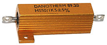
An aluminium-encased power resistor rated for dissipation of 50 W when mounted on a heat-sink
Power resistors are required to dissipate substantial amounts of power and are typically used in power supplies, power conversion circuits, and power amplifiers; this designation is loosely applied to resistors with power ratings of 1 watt or greater. Power resistors are physically larger and may not use the preferred values, color codes, and external packages described below.
If the average power dissipated by a resistor is more than its power rating, damage to the resistor may occur, permanently altering its resistance; this is distinct from the reversible change in resistance due to its temperature coefficient when it warms. Excessive power dissipation may raise the temperature of the resistor to a point where it can burn the circuit board or adjacent components, or even cause a fire. There are flameproof resistors that will not produce flames with any overload of any duration.
Resistors may be specified with higher rated dissipation than is experienced in service to account for poor air circulation, high altitude, or high operating temperature.
All resistors have a maximum voltage rating; this may limit the power dissipation for higher resistance values.[7] For instance, among 1⁄4 watt resistors (a very common sort of leaded resistor) one is listed with a resistance of 100 MΩ[8] and a maximum rated voltage of 750 V. However even placing 750 V across a 100 MΩ resistor continuously would only result in a power dissipation of less than 6 mW, making the nominal 1⁄4 watt rating meaningless.

VZR power resistor 1.5 kΩ 12 W, manufactured in 1963 in the Soviet Union
Nonideal properties
Practical resistors have a series inductance and a small parallel capacitance; these specifications can be important in high-frequency applications. In a low-noise amplifier or pre-amp, the noise characteristics of a resistor may be an issue.
In some precision applications, the temperature coefficient of the resistance may also be of concern.
The unwanted inductance, excess noise, and temperature coefficient are mainly dependent on the technology used in manufacturing the resistor. They are not normally specified individually for a particular family of resistors manufactured using a particular technology.[9] A family of discrete resistors may also be characterized according to its form factor, that is, the size of the device and the position of its leads (or terminals). This is relevant in the practical manufacturing of circuits that may use them.
Practical resistors are also specified as having a maximum power rating which must exceed the anticipated power dissipation of that resistor in a particular circuit: this is mainly of concern in power electronics applications.
Resistors with higher power ratings are physically larger and may require heat sinks. In a high-voltage circuit, attention must sometimes be paid to the rated maximum working voltage of the resistor. While there is no minimum working voltage for a given resistor, failure to account for a resistor’s maximum rating may cause the resistor to incinerate when current is run through it.
Fixed resistors

A single in line (SIL) resistor package with 8 individual 47 ohm resistors. This package is also known as a SIP-9. One end of each resistor is connected to a separate pin and the other ends are all connected together to the remaining (common) pin – pin 1, at the end identified by the white dot.
Lead arrangements

Axial resistors with wire leads for through-hole mounting
Through-hole components typically have «leads» (pronounced ) leaving the body «axially», that is, on a line parallel with the part’s longest axis. Others have leads coming off their body «radially» instead. Other components may be SMT (surface mount technology), while high power resistors may have one of their leads designed into the heat sink.
Carbon composition

Old style «dog bone» resistors with «body, tip, dot» color code marking

Three carbon composition resistors in a 1960s valve (vacuum tube) radio
Carbon composition resistors (CCR) consist of a solid cylindrical resistive element with embedded wire leads or metal end caps to which the lead wires are attached. The body of the resistor is protected with paint or plastic. Early 20th-century carbon composition resistors had uninsulated bodies; the lead wires were wrapped around the ends of the resistance element rod and soldered. The completed resistor was painted for color-coding of its value.
The resistive element in carbon composition resistors is made from a mixture of finely powdered carbon and an insulating material, usually ceramic. A resin holds the mixture together. The resistance is determined by the ratio of the fill material (the powdered ceramic) to the carbon. Higher concentrations of carbon, which is a good conductor, result in lower resistances. Carbon composition resistors were commonly used in the 1960s and earlier, but are not popular for general use now as other types have better specifications, such as tolerance, voltage dependence, and stress. Carbon composition resistors change value when stressed with over-voltages. Moreover, if internal moisture content, such as from exposure for some length of time to a humid environment, is significant, soldering heat creates a non-reversible change in resistance value. Carbon composition resistors have poor stability with time and were consequently factory sorted to, at best, only 5% tolerance.[10] These resistors are non-inductive, which provides benefits when used in voltage pulse reduction and surge protection applications.[11] Carbon composition resistors have higher capability to withstand overload relative to the component’s size.[12]
Carbon composition resistors are still available, but relatively expensive. Values ranged from fractions of an ohm to 22 megohms. Due to their high price, these resistors are no longer used in most applications. However, they are used in power supplies and welding controls.[12] They are also in demand for repair of vintage electronic equipment where authenticity is a factor.
Carbon pile
A carbon pile resistor is made of a stack of carbon disks compressed between two metal contact plates. Adjusting the clamping pressure changes the resistance between the plates. These resistors are used when an adjustable load is required, such as in testing automotive batteries or radio transmitters. A carbon pile resistor can also be used as a speed control for small motors in household appliances (sewing machines, hand-held mixers) with ratings up to a few hundred watts.[13] A carbon pile resistor can be incorporated in automatic voltage regulators for generators, where the carbon pile controls the field current to maintain relatively constant voltage.[14] This principle is also applied in the carbon microphone.
Carbon film

Carbon film resistor with exposed carbon spiral (Tesla TR-212 1 kΩ)
In manufacturing carbon film resistors, a carbon film is deposited on an insulating substrate, and a helix is cut in it to create a long, narrow resistive path. Varying shapes, coupled with the resistivity of amorphous carbon (ranging from 500 to 800 μΩ m), can provide a wide range of resistance values. Carbon film resistors feature lower noise compared to carbon composition resistors because of the precise distribution of the pure graphite without binding.[15] Carbon film resistors feature a power rating range of 0.125 W to 5 W at 70 °C. Resistances available range from 1 ohm to 10 megaohm. The carbon film resistor has an operating temperature range of −55 °C to 155 °C. It has 200 to 600 volts maximum working voltage range. Special carbon film resistors are used in applications requiring high pulse stability.[12]
Printed carbon resistors

Carbon resistors (black rectangles) printed directly onto the SMD pads on the PCB of a Psion Organiser II from 1989
Carbon composition resistors can be printed directly onto printed circuit board (PCB) substrates as part of the PCB manufacturing process. Although this technique is more common on hybrid PCB modules, it can also be used on standard fibreglass PCBs. Tolerances are typically quite large and can be in the order of 30%. A typical application would be non-critical pull-up resistors.
Thick and thin film
Laser Trimmed Precision Thin Film Resistor Network from Fluke, used in the Keithley DMM7510 multimeter. Ceramic backed with glass hermetic seal cover.
Thick film resistors became popular during the 1970s, and most SMD (surface mount device) resistors today are of this type. The resistive element of thick films is 1000 times thicker than thin films,[16] but the principal difference is how the film is applied to the cylinder (axial resistors) or the surface (SMD resistors).
Thin film resistors are made by sputtering (a method of vacuum deposition) the resistive material onto an insulating substrate. The film is then etched in a similar manner to the old (subtractive) process for making printed circuit boards; that is, the surface is coated with a photo-sensitive material, covered by a pattern film, irradiated with ultraviolet light, and then the exposed photo-sensitive coating is developed, and underlying thin film is etched away.
Thick film resistors are manufactured using screen and stencil printing processes.[12]
Because the time during which the sputtering is performed can be controlled, the thickness of the thin film can be accurately controlled. The type of material also varies, consisting of one or more ceramic (cermet) conductors such as tantalum nitride (TaN), ruthenium oxide (RuO
2), lead oxide (PbO), bismuth ruthenate (Bi
2Ru
2O
7), nickel chromium (NiCr), or bismuth iridate (Bi
2Ir
2O
7).
The resistance of both thin and thick film resistors after manufacture is not highly accurate; they are usually trimmed to an accurate value by abrasive or laser trimming. Thin film resistors are usually specified with tolerances of 1% and 5%, and with temperature coefficients of 5 to 50 ppm/K. They also have much lower noise levels, on the level of 10–100 times less than thick film resistors.[17] Thick film resistors may use the same conductive ceramics, but they are mixed with sintered (powdered) glass and a carrier liquid so that the composite can be screen-printed. This composite of glass and conductive ceramic (cermet) material is then fused (baked) in an oven at about 850 °C.
When first manufactured, thick film resistors had tolerances of 5%, but standard tolerances have improved to 2% or 1% in the last few decades.[timeframe?] Temperature coefficients of thick film resistors are typically ±200 or ±250 ppm/K; a 40-kelvin (70 °F) temperature change can change the resistance by 1%.
Thin film resistors are usually far more expensive than thick film resistors. For example, SMD thin film resistors, with 0.5% tolerances and with 25 ppm/K temperature coefficients, when bought in full size reel quantities, are about twice the cost of 1%, 250 ppm/K thick film resistors.
Metal film
A common type of axial-leaded resistor today is the metal-film resistor. Metal Electrode Leadless Face (MELF) resistors often use the same technology.
Metal film resistors are usually coated with nickel chromium (NiCr), but might be coated with any of the cermet materials listed above for thin film resistors. Unlike thin film resistors, the material may be applied using different techniques than sputtering (though this is one technique used). The resistance value is determined by cutting a helix through the coating rather than by etching, similar to the way carbon resistors are made. The result is a reasonable tolerance (0.5%, 1%, or 2%) and a temperature coefficient that is generally between 50 and 100 ppm/K.[18] Metal film resistors possess good noise characteristics and low non-linearity due to a low voltage coefficient. They are also beneficial due to long-term stability.[12]
Metal oxide film
Metal-oxide film resistors are made of metal oxides which results in a higher operating temperature and greater stability and reliability than metal film. They are used in applications with high endurance demands.
Wire wound

High-power wire wound resistors used for dynamic braking on an electric railway car. Such resistors may dissipate many kilowatts for an extended length of time.

Wirewound resistors are commonly made by winding a metal wire, usually nichrome, around a ceramic, plastic, or fiberglass core. The ends of the wire are soldered or welded to two caps or rings, attached to the ends of the core. The assembly is protected with a layer of paint, molded plastic, or an enamel coating baked at high temperature. These resistors are designed to withstand unusually high temperatures of up to 450 °C.[12] Wire leads in low power wirewound resistors are usually between 0.6 and 0.8 mm in diameter and tinned for ease of soldering. For higher power wirewound resistors, either a ceramic outer case or an aluminum outer case on top of an insulating layer is used. If the outer case is ceramic, such resistors are sometimes described as «cement» resistors, though they do not actually contain any traditional cement. The aluminum-cased types are designed to be attached to a heat sink to dissipate the heat; the rated power is dependent on being used with a suitable heat sink, e.g., a 50 W power rated resistor overheats at a fraction of the power dissipation if not used with a heat sink. Large wirewound resistors may be rated for 1,000 watts or more.
Because wirewound resistors are coils they have more undesirable inductance than other types of resistor. However, winding the wire in sections with alternately reversed direction can minimize inductance. Other techniques employ bifilar winding, or a flat thin former (to reduce cross-section area of the coil). For the most demanding circuits, resistors with Ayrton–Perry winding are used.
Applications of wirewound resistors are similar to those of composition resistors with the exception of high frequency applications. The high frequency response of wirewound resistors is substantially worse than that of a composition resistor.[12]
Metal foil resistor

In 1960, Felix Zandman and Sidney J. Stein[19] presented a development of resistor film of very high stability.
The primary resistance element of a foil resistor is a chromium nickel alloy foil several micrometers thick. Chromium nickel alloys are characterized by having a large electrical resistance (about 58 times that of copper), a small temperature coefficient and high resistance to oxidation. Examples are Chromel A and Nichrome V, whose typical composition is 80 Ni and 20 Cr, with a melting point of 1420 °C. When iron is added, the chromium nickel alloy becomes more ductile. The Nichrome and Chromel C are examples of an alloy containing iron. The composition typical of Nichrome is 60 Ni, 12 Cr, 26 Fe, 2 Mn and Chromel C, 64 Ni, 11 Cr, Fe 25. The melting temperature of these alloys are 1350 °C and 1390 °C, respectively.[20][full citation needed]
Since their introduction in the 1960s, foil resistors have had the best precision and stability of any resistor available. One of the important parameters of stability is the temperature coefficient of resistance (TCR). The TCR of foil resistors is extremely low, and has been further improved over the years. One range of ultra-precision foil resistors offers a TCR of 0.14 ppm/°C, tolerance ±0.005%, long-term stability (1 year) 25 ppm, (3 years) 50 ppm (further improved 5-fold by hermetic sealing), stability under load (2000 hours) 0.03%, thermal EMF 0.1 μV/°C, noise −42 dB, voltage coefficient 0.1 ppm/V, inductance 0.08 μH, capacitance 0.5 pF.[21]
The thermal stability of this type of resistor also has to do with the opposing effects of the metal’s electrical resistance increasing with temperature, and being reduced by thermal expansion leading to an increase in thickness of the foil, whose other dimensions are constrained by a ceramic substrate.[citation needed]
Ammeter shunts
An ammeter shunt is a special type of current-sensing resistor, having four terminals and a value in milliohms or even micro-ohms. Current-measuring instruments, by themselves, can usually accept only limited currents. To measure high currents, the current passes through the shunt across which the voltage drop is measured and interpreted as current. A typical shunt consists of two solid metal blocks, sometimes brass, mounted on an insulating base. Between the blocks, and soldered or brazed to them, are one or more strips of low temperature coefficient of resistance (TCR) manganin alloy. Large bolts threaded into the blocks make the current connections, while much smaller screws provide volt meter connections. Shunts are rated by full-scale current, and often have a voltage drop of 50 mV at rated current. Such meters are adapted to the shunt full current rating by using an appropriately marked dial face; no change need to be made to the other parts of the meter.
Grid resistor
In heavy-duty industrial high-current applications, a grid resistor is a large convection-cooled lattice of stamped metal alloy strips connected in rows between two electrodes. Such industrial grade resistors can be as large as a refrigerator; some designs can handle over 500 amperes of current, with a range of resistances extending lower than 0.04 ohms. They are used in applications such as dynamic braking and load banking for locomotives and trams, neutral grounding for industrial AC distribution, control loads for cranes and heavy equipment, load testing of generators and harmonic filtering for electric substations.[22]
The term grid resistor is sometimes used to describe a resistor of any type connected to the control grid of a vacuum tube. This is not a resistor technology; it is an electronic circuit topology.
Special varieties
- Cermet
- Phenolic
- Tantalum
- Water resistor
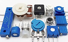
Variable resistors
Adjustable resistors
A resistor may have one or more fixed tapping points so that the resistance can be changed by moving the connecting wires to different terminals. Some wirewound power resistors have a tapping point that can slide along the resistance element, allowing a larger or smaller part of the resistance to be used.
Where continuous adjustment of the resistance value during operation of equipment is required, the sliding resistance tap can be connected to a knob accessible to an operator. Such a device is called a rheostat and has two terminals.
Potentiometers
Typical panel mount potentiometer

Drawing of potentiometer with case cut away, showing parts: (A) shaft, (B) stationary carbon composition resistance element, (C) phosphor bronze wiper, (D) shaft attached to wiper, (E, G) terminals connected to ends of resistance element, (F) terminal connected to wiper.
A potentiometer (colloquially, pot) is a three-terminal resistor with a continuously adjustable tapping point controlled by rotation of a shaft or knob or by a linear slider.[23] The name potentiometer comes from its function as an adjustable voltage divider to provide a variable potential at the terminal connected to the tapping point. Volume control in an audio device is a common application of a potentiometer. A typical low power potentiometer (see drawing) is constructed of a flat resistance element (B) of carbon composition, metal film, or conductive plastic, with a springy phosphor bronze wiper contact (C) which moves along the surface. An alternate construction is resistance wire wound on a form, with the wiper sliding axially along the coil.[23] These have lower resolution, since as the wiper moves the resistance changes in steps equal to the resistance of a single turn.[23]
High-resolution multiturn potentiometers are used in precision applications. These have wire-wound resistance elements typically wound on a helical mandrel, with the wiper moving on a helical track as the control is turned, making continuous contact with the wire. Some include a conductive-plastic resistance coating over the wire to improve resolution. These typically offer ten turns of their shafts to cover their full range. They are usually set with dials that include a simple turns counter and a graduated dial, and can typically achieve three-digit resolution. Electronic analog computers used them in quantity for setting coefficients and delayed-sweep oscilloscopes of recent decades included one on their panels.
Resistance decade boxes

A resistance decade box or resistor substitution box is a unit containing resistors of many values, with one or more mechanical switches which allow any one of various discrete resistances offered by the box to be dialed in. Usually the resistance is accurate to high precision, ranging from laboratory/calibration grade accuracy of 20 parts per million, to field grade at 1%. Inexpensive boxes with lesser accuracy are also available. All types offer a convenient way of selecting and quickly changing a resistance in laboratory, experimental and development work without needing to attach resistors one by one, or even stock each value. The range of resistance provided, the maximum resolution, and the accuracy characterize the box. For example, one box offers resistances from 0 to 100 megohms, maximum resolution 0.1 ohm, accuracy 0.1%.[24]
Special devices
There are various devices whose resistance changes with various quantities. The resistance of NTC thermistors exhibit a strong negative temperature coefficient, making them useful for measuring temperatures. Since their resistance can be large until they are allowed to heat up due to the passage of current, they are also commonly used to prevent excessive current surges when equipment is powered on. Similarly, the resistance of a humistor varies with humidity. One sort of photodetector, the photoresistor, has a resistance which varies with illumination.
The strain gauge, invented by Edward E. Simmons and Arthur C. Ruge in 1938, is a type of resistor that changes value with applied strain. A single resistor may be used, or a pair (half bridge), or four resistors connected in a Wheatstone bridge configuration. The strain resistor is bonded with adhesive to an object that is subjected to mechanical strain. With the strain gauge and a filter, amplifier, and analog/digital converter, the strain on an object can be measured.
A related but more recent invention uses a Quantum Tunnelling Composite to sense mechanical stress. It passes a current whose magnitude can vary by a factor of 1012 in response to changes in applied pressure.
Measurement
The value of a resistor can be measured with an ohmmeter, which may be one function of a multimeter. Usually, probes on the ends of test leads connect to the resistor. A simple ohmmeter may apply a voltage from a battery across the unknown resistor (with an internal resistor of a known value in series) producing a current which drives a meter movement. The current, in accordance with Ohm’s law, is inversely proportional to the sum of the internal resistance and the resistor being tested, resulting in an analog meter scale which is very non-linear, calibrated from infinity to 0 ohms. A digital multimeter, using active electronics, may instead pass a specified current through the test resistance. The voltage generated across the test resistance in that case is linearly proportional to its resistance, which is measured and displayed. In either case the low-resistance ranges of the meter pass much more current through the test leads than do high-resistance ranges. This allows for the voltages present to be at reasonable levels (generally below 10 volts) but still measurable.
Measuring low-value resistors, such as fractional-ohm resistors, with acceptable accuracy requires four-terminal connections. One pair of terminals applies a known, calibrated current to the resistor, while the other pair senses the voltage drop across the resistor. Some laboratory quality ohmmeters, milliohmmeters, and even some of the better digital multimeters sense using four input terminals for this purpose, which may be used with special test leads called Kelvin clips. Each of the two clips has a pair of jaws insulated from each other. One side of each clip applies the measuring current, while the other connections are only to sense the voltage drop. The resistance is again calculated using Ohm’s Law as the measured voltage divided by the applied current.
Standards
Production resistors
Resistor characteristics are quantified and reported using various national standards. In the US, MIL-STD-202[25] contains the relevant test methods to which other standards refer.
There are various standards specifying properties of resistors for use in equipment:
- IEC 60062 (IEC 62) / DIN 40825 / BS 1852 / IS 8186 / JIS C 5062 etc. (Resistor color code, RKM code, date code)
- EIA RS-279 / DIN 41429 (Resistor color code)
- IEC 60063 (IEC 63) / JIS C 5063 (Standard E series values)
- MIL-PRF-26
- MIL-PRF-39007 (Fixed power, established reliability)
- MIL-PRF-55342 (Surface-mount thick and thin film)
- MIL-PRF-914
- MIL-R-11 Standard Canceled
- MIL-R-39017 (Fixed, General Purpose, Established Reliability)
- MIL-PRF-32159 (zero ohm jumpers)
- UL 1412 (fusing and temperature limited resistors)[26]
There are other United States military procurement MIL-R- standards.
Resistance standards
The primary standard for resistance, the «mercury ohm» was initially defined in 1884 in as a column of mercury 106.3 cm long and 1 square millimeter in cross-section, at 0 degrees Celsius. Difficulties in precisely measuring the physical constants to replicate this standard result in variations of as much as 30 ppm. From 1900 the mercury ohm was replaced with a precision machined plate of manganin.[27] Since 1990 the international resistance standard has been based on the quantized Hall effect discovered by Klaus von Klitzing, for which he won the Nobel Prize in Physics in 1985.[28]
Resistors of extremely high precision are manufactured for calibration and laboratory use. They may have four terminals, using one pair to carry an operating current and the other pair to measure the voltage drop; this eliminates errors caused by voltage drops across the lead resistances, because no charge flows through voltage sensing leads. It is important in small value resistors (100–0.0001 ohm) where lead resistance is significant or even comparable with respect to resistance standard value.[29]
Resistor marking

Wheel-based RMA Resistor Color Code guide. Circa 1945–1950.
Axial resistors’ cases are usually tan, brown, blue, or green (though other colors are occasionally found as well, such as dark red or dark gray), and display 3–6 colored stripes that indicate resistance (and by extension tolerance), and may include bands to indicate the temperature coefficient and reliability class. In four-striped resistors, the first two stripes represent the first two digits of the resistance in ohms, the third represents a multiplier, and the fourth the tolerance (which if absent, denotes ±20%). For five- and six- striped resistors the third band is the third digit, the fourth is the multiplier and the fifth is the tolerance; a sixth stripe represents the temperature coefficient. The power rating of the resistor is usually not marked and is deduced from its size.
Surface-mount resistors are marked numerically.
Early 20th century resistors, essentially uninsulated, were dipped in paint to cover their entire body for color-coding. This base color represented the first digit. A second color of paint was applied to one end of the element to represent a second digit, and a color dot (or band) in the middle provided the third digit. The rule was «body, tip, dot», providing two significant digits for value and the decimal multiplier, in that sequence. Default tolerance was ±20%. Closer-tolerance resistors had silver (±10%) or gold-colored (±5%) paint on the other end.
Preferred values
Early resistors were made in more or less arbitrary round numbers; a series might have 100, 125, 150, 200, 300, etc.[30] Early power wirewound resistors, such as brown vitreous-enameled types, were made with a system of preferred values like some of those mentioned here. Resistors as manufactured are subject to a certain percentage tolerance, and it makes sense to manufacture values that correlate with the tolerance, so that the actual value of a resistor overlaps slightly with its neighbors. Wider spacing leaves gaps; narrower spacing increases manufacturing and inventory costs to provide resistors that are more or less interchangeable.
A logical scheme is to produce resistors in a range of values which increase in a geometric progression, so that each value is greater than its predecessor by a fixed multiplier or percentage, chosen to match the tolerance of the range. For example, for a tolerance of ±20% it makes sense to have each resistor about 1.5 times its predecessor, covering a decade in 6 values. More precisely, the factor used is 1.4678 ≈  , giving values of 1.47, 2.15, 3.16, 4.64, 6.81, 10 for the 1–10-decade (a decade is a range increasing by a factor of 10; 0.1–1 and 10–100 are other examples); these are rounded in practice to 1.5, 2.2, 3.3, 4.7, 6.8, 10; followed by 15, 22, 33, … and preceded by … 0.47, 0.68, 1. This scheme has been adopted as the E6 series of the IEC 60063 preferred number values. There are also E12, E24, E48, E96 and E192 series for components of progressively finer resolution, with 12, 24, 48, 96, and 192 different values within each decade. The actual values used are in the IEC 60063 lists of preferred numbers.
A resistor of 100 ohms ±20% would be expected to have a value between 80 and 120 ohms; its E6 neighbors are 68 (54–82) and 150 (120–180) ohms. A sensible spacing, E6 is used for ±20% components; E12 for ±10%; E24 for ±5%; E48 for ±2%, E96 for ±1%; E192 for ±0.5% or better. Resistors are manufactured in values from a few milliohms to about a gigaohm in IEC60063 ranges appropriate for their tolerance. Manufacturers may sort resistors into tolerance-classes based on measurement. Accordingly, a selection of 100 ohms resistors with a tolerance of ±10%, might not lie just around 100 ohm (but no more than 10% off) as one would expect (a bell-curve), but rather be in two groups – either between 5 and 10% too high or 5 to 10% too low (but not closer to 100 ohm than that) because any resistors the factory had measured as being less than 5% off would have been marked and sold as resistors with only ±5% tolerance or better. When designing a circuit, this may become a consideration. This process of sorting parts based on post-production measurement is known as «binning», and can be applied to other components than resistors (such as speed grades for CPUs).
SMT resistors
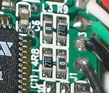
This image shows four surface-mount resistors (the component at the upper left is a capacitor) including two zero-ohm resistors. Zero-ohm links are often used instead of wire links, so that they can be inserted by a resistor-inserting machine. Their resistance is negligible.
Surface mounted resistors of larger sizes (metric 1608 and above) are printed with numerical values in a code related to that used on axial resistors. Standard-tolerance surface-mount technology (SMT) resistors are marked with a three-digit code, in which the first two digits are the first two significant digits of the value and the third digit is the power of ten (the number of zeroes). For example:
- 334 = 33 × 104 Ω = 330 kΩ
- 222 = 22 × 102 Ω = 2.2 kΩ
- 473 = 47 × 103 Ω = 47 kΩ
- 105 = 10 × 105 Ω = 1 MΩ
Resistances less than 100 Ω are written: 100, 220, 470. The final zero represents ten to the power zero, which is 1. For example:
- 100 = 10 × 100 Ω = 10 Ω
- 220 = 22 × 100 Ω = 22 Ω
Sometimes these values are marked as 10 or 22 to prevent a mistake.
Resistances less than 10 Ω have ‘R’ to indicate the position of the decimal point (radix point). For example:
- 4R7 = 4.7 Ω
- R300 = 0.30 Ω
- 0R22 = 0.22 Ω
- 0R01 = 0.01 Ω
000 and 0000 sometimes appear as values on surface-mount zero-ohm links, since these have (approximately) zero resistance.
More recent surface-mount resistors are too small, physically, to permit practical markings to be applied.
Precision resistor markings
Many precision resistors, including surface mount and axial-lead types, are marked with a four-digit code. The first three digits are the significant figures and the fourth is the power of ten. For example:
- 1001 = 100 × 101 Ω = 1.00 kΩ
- 4992 = 499 × 102 Ω = 49.9 kΩ
- 1000 = 100 × 100 Ω = 100 Ω
Axial-lead precision resistors often use color code bands to represent this four-digit code.
EIA-96 marking
The former EIA-96 marking system now included in IEC 60062:2016 is a more compact marking system intended for physically small high-precision resistors. It uses a two-digit code plus a letter (a total of three alphanumeric characters) to indicate 1% resistance values to three significant digits.[31] The two digits (from «01» to «96») are a code that indicates one of the 96 «positions» in the standard E96 series of 1% resistor values. The uppercase letter is a code that indicates a power of ten multiplier. For example, the marking «01C» represents 10 kOhm; «10C» represents 12.4 kOhm; «96C» represents 97.6 kOhm.[32][33][34][35][36]
|
|
Industrial type designation
| Type no. | Power rating (watts) |
MIL-R-11 style |
MIL-R-39008 style |
|---|---|---|---|
| BB | 1⁄8 | RC05 | RCR05 |
| CB | 1⁄4 | RC07 | RCR07 |
| EB | 1⁄2 | RC20 | RCR20 |
| GB | 1 | RC32 | RCR32 |
| HB | 2 | RC42 | RCR42 |
| GM | 3 | — | — |
| HM | 4 | — | — |
| Industrial type designation | Tolerance | MIL designation |
|---|---|---|
| 5 | ±5% | J |
| 2 | ±20% | M |
| 1 | ±10% | K |
| — | ±2% | G |
| — | ±1% | F |
| — | ±0.5% | D |
| — | ±0.25% | C |
| — | ±0.1% | B |
Steps to find out the resistance or capacitance values:[37]
- First two letters gives the power dissipation capacity.
- Next three digits gives the resistance value.
- First two digits are the significant values
- Third digit is the multiplier.
- Final digit gives the tolerance.
If a resistor is coded:
- EB1041: power dissipation capacity = 1/2 watts, resistance value = 10×104±10% = between 9×10⁴ ohms and 11×104 ohms.
- CB3932: power dissipation capacity = 1/4 watts, resistance value = 39×103±20% = between 31.2×10³ and 46.8×10³ ohms.
Electrical and thermal noise
In amplifying faint signals, it is often necessary to minimize electronic noise, particularly in the first stage of amplification. As a dissipative element, even an ideal resistor naturally produces a randomly fluctuating voltage, or noise, across its terminals. This Johnson–Nyquist noise is a fundamental noise source which depends only upon the temperature and resistance of the resistor, and is predicted by the fluctuation–dissipation theorem. Using a larger value of resistance produces a larger voltage noise, whereas a smaller value of resistance generates more current noise, at a given temperature.
The thermal noise of a practical resistor may also be larger than the theoretical prediction and that increase is typically frequency-dependent. Excess noise of a practical resistor is observed only when current flows through it. This is specified in unit of μV/V/decade – μV of noise per volt applied across the resistor per decade of frequency. The μV/V/decade value is frequently given in dB so that a resistor with a noise index of 0 dB exhibits 1 μV (rms) of excess noise for each volt across the resistor in each frequency decade. Excess noise is thus an example of 1/f noise. Thick-film and carbon composition resistors generate more excess noise than other types at low frequencies. Wire-wound and thin-film resistors are often used for their better noise characteristics. Carbon composition resistors can exhibit a noise index of 0 dB while bulk metal foil resistors may have a noise index of −40 dB, usually making the excess noise of metal foil resistors insignificant.[38] Thin film surface mount resistors typically have lower noise and better thermal stability than thick film surface mount resistors. Excess noise is also size-dependent: in general, excess noise is reduced as the physical size of a resistor is increased (or multiple resistors are used in parallel), as the independently fluctuating resistances of smaller components tend to average out.
While not an example of «noise» per se, a resistor may act as a thermocouple, producing a small DC voltage differential across it due to the thermoelectric effect if its ends are at different temperatures. This induced DC voltage can degrade the precision of instrumentation amplifiers in particular. Such voltages appear in the junctions of the resistor leads with the circuit board and with the resistor body. Common metal film resistors show such an effect at a magnitude of about 20 μV/°C. Some carbon composition resistors can exhibit thermoelectric offsets as high as 400 μV/°C, whereas specially constructed resistors can reduce this number to 0.05 μV/°C. In applications where the thermoelectric effect may become important, care has to be taken to mount the resistors horizontally to avoid temperature gradients and to mind the air flow over the board.[39]
Failure modes
The failure rate of resistors in a properly designed circuit is low compared to other electronic components such as semiconductors and electrolytic capacitors. Damage to resistors most often occurs due to overheating when the average power delivered to it greatly exceeds its ability to dissipate heat (specified by the resistor’s power rating). This may be due to a fault external to the circuit but is frequently caused by the failure of another component (such as a transistor that shorts out) in the circuit connected to the resistor. Operating a resistor too close to its power rating can limit the resistor’s lifespan or cause a significant change in its resistance. A safe design generally uses overrated resistors in power applications to avoid this danger.
Low-power thin-film resistors can be damaged by long-term high-voltage stress, even below maximum specified voltage and below maximum power rating. This is often the case for the startup resistors feeding a switched-mode power supply integrated circuit.[citation needed]
When overheated, carbon-film resistors may decrease or increase in resistance.[40]
Carbon film and composition resistors can fail (open circuit) if running close to their maximum dissipation. This is also possible but less likely with metal film and wirewound resistors.
There can also be failure of resistors due to mechanical stress and adverse environmental factors including humidity. If not enclosed, wirewound resistors can corrode.
Surface mount resistors have been known to fail due to the ingress of sulfur into the internal makeup of the resistor. This sulfur chemically reacts with the silver layer to produce non-conductive silver sulfide. The resistor’s impedance goes to infinity. Sulfur resistant and anti-corrosive resistors are sold into automotive, industrial, and military applications. ASTM B809 is an industry standard that tests a part’s susceptibility to sulfur.
An alternative failure mode can be encountered where large value resistors are used (hundreds of kilohms and higher). Resistors are not only specified with a maximum power dissipation, but also for a maximum voltage drop. Exceeding this voltage causes the resistor to degrade slowly reducing in resistance. The voltage dropped across large value resistors can be exceeded before the power dissipation reaches its limiting value. Since the maximum voltage specified for commonly encountered resistors is a few hundred volts, this is a problem only in applications where these voltages are encountered.
Variable resistors can also degrade in a different manner, typically involving poor contact between the wiper and the body of the resistance. This may be due to dirt or corrosion and is typically perceived as «crackling» as the contact resistance fluctuates; this is especially noticed as the device is adjusted. This is similar to crackling caused by poor contact in switches, and like switches, potentiometers are to some extent self-cleaning: running the wiper across the resistance may improve the contact. Potentiometers which are seldom adjusted, especially in dirty or harsh environments, are most likely to develop this problem. When self-cleaning of the contact is insufficient, improvement can usually be obtained through the use of contact cleaner (also known as «tuner cleaner») spray. The crackling noise associated with turning the shaft of a dirty potentiometer in an audio circuit (such as the volume control) is greatly accentuated when an undesired DC voltage is present, often indicating the failure of a DC blocking capacitor in the circuit.
See also
- Circuit design
- Dummy load
- Electrical impedance
- High value resistors (electronics)
- Iron-hydrogen resistor
- Piezoresistive effect
- Shot noise
- Thermistor
- Trimmer (electronics)
References
- ^ Harder, Douglas Wilhelm. «Resistors: A Motor with a Constant Force (Force Source)». Department of Electrical and Computer Engineering, University of Waterloo. Retrieved 9 November 2014.
- ^ American Radio Relay League (ARRL) (2021). «Fundamental Theory—Circuits and Components». ARRL Handbook for Radio Communications (98 ed.). American Radio Relay League. ISBN 978-1-62595-139-7.
- ^ a b c Doug DeMaw, ed. (1968). «Electrical Laws and Circuits —Resistance». Radio Amateurs Handbook (45 ed.). American Radio Relay League.
- ^ Farago, P.S. (1961) An Introduction to Linear Network Analysis, pp. 18–21, The English Universities Press Ltd.
- ^ Wu, F. Y. (2004). «Theory of resistor networks: The two-point resistance». Journal of Physics A: Mathematical and General. 37 (26): 6653–6673. arXiv:math-ph/0402038. Bibcode:2004JPhA…37.6653W. doi:10.1088/0305-4470/37/26/004. S2CID 119611570.
- ^ Wu, Fa Yueh; Yang, Chen Ning (2009). Exactly Solved Models: A Journey in Statistical Mechanics : Selected Papers with Commentaries (1963–2008). World Scientific. pp. 489–. ISBN 978-981-281-388-6.
- ^ «Specifications and How to Interpret Them» (PDF). Stackpole Electronics. Retrieved July 6, 2021.
- ^ https://nl.farnell.com/te-connectivity/rgp0207chj100m/res-100m-5-250mw-axial-thick-film/dp/2805251[bare URL]
- ^ A family of resistors may also be characterized according to its critical resistance. Applying a constant voltage across resistors in that family below the critical resistance will exceed the maximum power rating first; resistances larger than the critical resistance fail first from exceeding the maximum voltage rating. See Middleton, Wendy; Van Valkenburg, Mac E. (2002). Reference data for engineers: radio, electronics, computer, and communications (9 ed.). Newnes. pp. 5–10. ISBN 0-7506-7291-9.
- ^ Harter, James H. and Lin, Paul Y. (1982) Essentials of electric circuits. Reston Publishing Company. pp. 96–97. ISBN 0-8359-1767-3.
- ^ HVR International (ed.). «SR Series: Surge Resistors for PCB Mounting». (PDF; 252 kB), 26 May 2005, retrieved 24 January 2017.
- ^ a b c d e f g Beyschlag, Vishay (2008). «Basics of Linear Fixed Resistors Application Note», Document Number 28771.
- ^ Morris, C. G. (ed.) (1992). Academic Press Dictionary of Science and Technology. Gulf Professional Publishing. p. 360. ISBN 0122004000.
- ^ Principles of automotive vehicles. United States Department of the Army (1985). p. 13
- ^ «Carbon Film Resistor». The Resistorguide. Retrieved 10 March 2013.
- ^ «Thick Film and Thin Film» (PDF). Digi-Key (SEI). Archived from the original (PDF) on 27 September 2011. Retrieved 23 July 2011.
- ^ «Thin and Thick film». resisitorguide.com. resistor guide. Retrieved 3 December 2017.
- ^ Kuhn, Kenneth A. «Measuring the Temperature Coefficient of a Resistor» (PDF). Archived from the original (PDF) on 2016-03-04. Retrieved 2010-03-18.
- ^ Zandman, F.; Stein, S. (1964). «A New Precision Film Resistor Exhibiting Bulk Properties». IEEE Transactions on Component Parts. 11 (2): 107–119. doi:10.1109/TCP.1964.1135008.
- ^ Procedures in Experimental Physics, John Strong, p. 546.
- ^ «Alpha Electronics Corp. Metal Foil Resistors». Alpha-elec.co.jp. Retrieved 2008-09-22.
- ^ «Grid Resistors: High Power/High Current». Milwaukee Resistor Corporation. Retrieved 14 May 2012.
- ^ a b c Mazda, F. F. (1981). Discrete Electronic Components. CUP Archive. pp. 57–61. ISBN 0521234700.
- ^ «Decade Box – Resistance Decade Boxes». Ietlabs.com. Retrieved 2008-09-22.
- ^ «Test method standard: electronic and electrical component parts» (PDF). Department of Defense. Archived from the original (PDF) on 2015-02-09.
- ^ Fusing Resistors and Temperature-Limited Resistors for Radio- and Television- Type Appliances UL 1412. ulstandardsinfonet.ul.com
- ^ Stability of Double-Walled Manganin Resistors Archived 2006-10-06 at the Wayback Machine. NIST.gov
- ^ Klaus von Klitzing The Quantized Hall Effect. Nobel lecture, December 9, 1985. nobelprize.org
- ^ «Standard Resistance Unit Type 4737B». Tinsley.co.uk. Archived from the original on 2008-08-21. Retrieved 2008-09-22.
- ^ «1940 Catalog – page 60 – Resistors». RadioShack. Archived from the original on 11 July 2017. Retrieved 11 July 2017.
- ^ «Chapter 2 — Resistor standards and codes».
- ^ «CRP0603 Series — Precision Chip Resistors». p. 3.
- ^ «Online calculator — EIA-96 SMD resistor».
- ^ «SMD Resistor Codes: How to Find the Value of SMD Resistors».
- ^ «Marking Codes used on Welwyn Chip Resistors». p. 2.
- ^ «Surface Mount Resistor: codes & markings».
- ^ Maini, A. K. (2008), Electronics and Communications Simplified, 9th ed., Khanna Publications. ISBN 817409217X
- ^ Audio Noise Reduction Through the Use of Bulk Metal Foil Resistors – «Hear the Difference» (PDF). Archived from the original (PDF) on 2013-01-19. Retrieved 2009-08-03., Application note AN0003, Vishay Intertechnology Inc, 12 July 2005.
- ^ Jung, Walt (2005). «Chapter 7 – Hardware and Housekeeping Techniques» (PDF). Op Amp Applications Handbook. p. 7.11. ISBN 0-7506-7844-5.
- ^ «Electronic components – resistors». Inspector’s Technical Guide. US Food and Drug Administration. 1978-01-16. Archived from the original on 2008-04-03. Retrieved 2008-06-11.
External links
![]()
Look up resistor in Wiktionary, the free dictionary.
- 4-terminal resistors – How ultra-precise resistors work
- Beginner’s guide to potentiometers, including description of different tapers
- Color Coded Resistance Calculator – archived with WayBack Machine
- Resistor Types – Does It Matter?
- Standard Resistors & Capacitor Values That Industry Manufactures
- Ask The Applications Engineer – Difference between types of resistors
- Resistors and their uses
|
An array of axial-lead resistors |
|
| Type | Passive |
|---|---|
| Working principle | Electric resistance |
| Electronic symbol | |
| IEEE schematic symbols |
Various resistor types of different shapes and sizes
A resistor is a passive two-terminal electrical component that implements electrical resistance as a circuit element. In electronic circuits, resistors are used to reduce current flow, adjust signal levels, to divide voltages, bias active elements, and terminate transmission lines, among other uses. High-power resistors that can dissipate many watts of electrical power as heat may be used as part of motor controls, in power distribution systems, or as test loads for generators.
Fixed resistors have resistances that only change slightly with temperature, time or operating voltage. Variable resistors can be used to adjust circuit elements (such as a volume control or a lamp dimmer), or as sensing devices for heat, light, humidity, force, or chemical activity.
Resistors are common elements of electrical networks and electronic circuits and are ubiquitous in electronic equipment. Practical resistors as discrete components can be composed of various compounds and forms. Resistors are also implemented within integrated circuits.
The electrical function of a resistor is specified by its resistance: common commercial resistors are manufactured over a range of more than nine orders of magnitude. The nominal value of the resistance falls within the manufacturing tolerance, indicated on the component.
Electronic symbols and notation
Two typical schematic diagram symbols are as follows:
-
ANSI-style: (a) resistor, (b) rheostat (variable resistor), and (c) potentiometer
-
IEC resistor symbol
The notation to state a resistor’s value in a circuit diagram varies.
One common scheme is the RKM code following IEC 60062. Rather than using a decimal separator, this notation uses a letter loosely associated with SI prefixes corresponding with the part’s resistance. For example, 8K2 as part marking code, in a circuit diagram or in a bill of materials (BOM) indicates a resistor value of 8.2 kΩ. Additional zeros imply a tighter tolerance, for example 15M0 for three significant digits. When the value can be expressed without the need for a prefix (that is, multiplicator 1), an «R» is used instead of the decimal separator. For example, 1R2 indicates 1.2 Ω, and 18R indicates 18 Ω.
Theory of operation
The hydraulic analogy compares electric current flowing through circuits to water flowing through pipes. When a pipe (left) is clogged with hair (right), it takes a larger pressure to achieve the same flow of water. Pushing electric current through a large resistance is like pushing water through a pipe clogged with hair: It requires a larger push (voltage) to drive the same flow (electric current).[1]
Ohm’s law
The behaviour of an ideal resistor is described by Ohm’s law:
Ohm’s law states that the voltage () across a resistor is proportional to the current () passing through it, where the constant of proportionality is the resistance (). For example, if a 300-ohm resistor is attached across the terminals of a 12-volt battery, then a current of 12 / 300 = 0.04 amperes flows through that resistor.
The ohm (symbol: Ω) is the SI unit of electrical resistance, named after Georg Simon Ohm. An ohm is equivalent to a volt per ampere. Since resistors are specified and manufactured over a very large range of values, the derived units of milliohm (1 mΩ = 10−3 Ω), kilohm (1 kΩ = 103 Ω), and megohm (1 MΩ = 106 Ω) are also in common usage.[2][3]: p.20
Series and parallel resistors
The total resistance of resistors connected in series is the sum of their individual resistance values.
The total resistance of resistors connected in parallel is the reciprocal of the sum of the reciprocals of the individual resistors.[3]: p.20ff
For example, a 10 ohm resistor connected in parallel with a 5 ohm resistor and a 15 ohm resistor produces 1/1/10 + 1/5 + 1/15 ohms of resistance, or 30/11 = 2.727 ohms.
A resistor network that is a combination of parallel and series connections can be broken up into smaller parts that are either one or the other. Some complex networks of resistors cannot be resolved in this manner, requiring more sophisticated circuit analysis. Generally, the Y-Δ transform, or matrix methods can be used to solve such problems.[4][5][6]
Power dissipation
At any instant, the power P (watts) consumed by a resistor of resistance R (ohms) is calculated as:
where V (volts) is the voltage across the resistor and I (amps) is the current flowing through it. Using Ohm’s law, the two other forms can be derived. This power is converted into heat which must be dissipated by the resistor’s package before its temperature rises excessively.[3]: p.22
Resistors are rated according to their maximum power dissipation. Discrete resistors in solid-state electronic systems are typically rated as 1⁄10, 1⁄8, or 1⁄4 watt. They usually absorb much less than a watt of electrical power and require little attention to their power rating.
An aluminium-encased power resistor rated for dissipation of 50 W when mounted on a heat-sink
Power resistors are required to dissipate substantial amounts of power and are typically used in power supplies, power conversion circuits, and power amplifiers; this designation is loosely applied to resistors with power ratings of 1 watt or greater. Power resistors are physically larger and may not use the preferred values, color codes, and external packages described below.
If the average power dissipated by a resistor is more than its power rating, damage to the resistor may occur, permanently altering its resistance; this is distinct from the reversible change in resistance due to its temperature coefficient when it warms. Excessive power dissipation may raise the temperature of the resistor to a point where it can burn the circuit board or adjacent components, or even cause a fire. There are flameproof resistors that will not produce flames with any overload of any duration.
Resistors may be specified with higher rated dissipation than is experienced in service to account for poor air circulation, high altitude, or high operating temperature.
All resistors have a maximum voltage rating; this may limit the power dissipation for higher resistance values.[7] For instance, among 1⁄4 watt resistors (a very common sort of leaded resistor) one is listed with a resistance of 100 MΩ[8] and a maximum rated voltage of 750 V. However even placing 750 V across a 100 MΩ resistor continuously would only result in a power dissipation of less than 6 mW, making the nominal 1⁄4 watt rating meaningless.
VZR power resistor 1.5 kΩ 12 W, manufactured in 1963 in the Soviet Union
Nonideal properties
Practical resistors have a series inductance and a small parallel capacitance; these specifications can be important in high-frequency applications. In a low-noise amplifier or pre-amp, the noise characteristics of a resistor may be an issue.
In some precision applications, the temperature coefficient of the resistance may also be of concern.
The unwanted inductance, excess noise, and temperature coefficient are mainly dependent on the technology used in manufacturing the resistor. They are not normally specified individually for a particular family of resistors manufactured using a particular technology.[9] A family of discrete resistors may also be characterized according to its form factor, that is, the size of the device and the position of its leads (or terminals). This is relevant in the practical manufacturing of circuits that may use them.
Practical resistors are also specified as having a maximum power rating which must exceed the anticipated power dissipation of that resistor in a particular circuit: this is mainly of concern in power electronics applications.
Resistors with higher power ratings are physically larger and may require heat sinks. In a high-voltage circuit, attention must sometimes be paid to the rated maximum working voltage of the resistor. While there is no minimum working voltage for a given resistor, failure to account for a resistor’s maximum rating may cause the resistor to incinerate when current is run through it.
Fixed resistors
A single in line (SIL) resistor package with 8 individual 47 ohm resistors. This package is also known as a SIP-9. One end of each resistor is connected to a separate pin and the other ends are all connected together to the remaining (common) pin – pin 1, at the end identified by the white dot.
Lead arrangements
Axial resistors with wire leads for through-hole mounting
Through-hole components typically have «leads» (pronounced ) leaving the body «axially», that is, on a line parallel with the part’s longest axis. Others have leads coming off their body «radially» instead. Other components may be SMT (surface mount technology), while high power resistors may have one of their leads designed into the heat sink.
Carbon composition
Old style «dog bone» resistors with «body, tip, dot» color code marking
Three carbon composition resistors in a 1960s valve (vacuum tube) radio
Carbon composition resistors (CCR) consist of a solid cylindrical resistive element with embedded wire leads or metal end caps to which the lead wires are attached. The body of the resistor is protected with paint or plastic. Early 20th-century carbon composition resistors had uninsulated bodies; the lead wires were wrapped around the ends of the resistance element rod and soldered. The completed resistor was painted for color-coding of its value.
The resistive element in carbon composition resistors is made from a mixture of finely powdered carbon and an insulating material, usually ceramic. A resin holds the mixture together. The resistance is determined by the ratio of the fill material (the powdered ceramic) to the carbon. Higher concentrations of carbon, which is a good conductor, result in lower resistances. Carbon composition resistors were commonly used in the 1960s and earlier, but are not popular for general use now as other types have better specifications, such as tolerance, voltage dependence, and stress. Carbon composition resistors change value when stressed with over-voltages. Moreover, if internal moisture content, such as from exposure for some length of time to a humid environment, is significant, soldering heat creates a non-reversible change in resistance value. Carbon composition resistors have poor stability with time and were consequently factory sorted to, at best, only 5% tolerance.[10] These resistors are non-inductive, which provides benefits when used in voltage pulse reduction and surge protection applications.[11] Carbon composition resistors have higher capability to withstand overload relative to the component’s size.[12]
Carbon composition resistors are still available, but relatively expensive. Values ranged from fractions of an ohm to 22 megohms. Due to their high price, these resistors are no longer used in most applications. However, they are used in power supplies and welding controls.[12] They are also in demand for repair of vintage electronic equipment where authenticity is a factor.
Carbon pile
A carbon pile resistor is made of a stack of carbon disks compressed between two metal contact plates. Adjusting the clamping pressure changes the resistance between the plates. These resistors are used when an adjustable load is required, such as in testing automotive batteries or radio transmitters. A carbon pile resistor can also be used as a speed control for small motors in household appliances (sewing machines, hand-held mixers) with ratings up to a few hundred watts.[13] A carbon pile resistor can be incorporated in automatic voltage regulators for generators, where the carbon pile controls the field current to maintain relatively constant voltage.[14] This principle is also applied in the carbon microphone.
Carbon film
Carbon film resistor with exposed carbon spiral (Tesla TR-212 1 kΩ)
In manufacturing carbon film resistors, a carbon film is deposited on an insulating substrate, and a helix is cut in it to create a long, narrow resistive path. Varying shapes, coupled with the resistivity of amorphous carbon (ranging from 500 to 800 μΩ m), can provide a wide range of resistance values. Carbon film resistors feature lower noise compared to carbon composition resistors because of the precise distribution of the pure graphite without binding.[15] Carbon film resistors feature a power rating range of 0.125 W to 5 W at 70 °C. Resistances available range from 1 ohm to 10 megaohm. The carbon film resistor has an operating temperature range of −55 °C to 155 °C. It has 200 to 600 volts maximum working voltage range. Special carbon film resistors are used in applications requiring high pulse stability.[12]
Printed carbon resistors
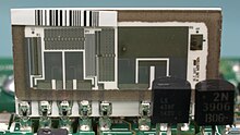
Carbon resistors (black rectangles) printed directly onto the SMD pads on the PCB of a Psion Organiser II from 1989
Carbon composition resistors can be printed directly onto printed circuit board (PCB) substrates as part of the PCB manufacturing process. Although this technique is more common on hybrid PCB modules, it can also be used on standard fibreglass PCBs. Tolerances are typically quite large and can be in the order of 30%. A typical application would be non-critical pull-up resistors.
Thick and thin film
Laser Trimmed Precision Thin Film Resistor Network from Fluke, used in the Keithley DMM7510 multimeter. Ceramic backed with glass hermetic seal cover.
Thick film resistors became popular during the 1970s, and most SMD (surface mount device) resistors today are of this type. The resistive element of thick films is 1000 times thicker than thin films,[16] but the principal difference is how the film is applied to the cylinder (axial resistors) or the surface (SMD resistors).
Thin film resistors are made by sputtering (a method of vacuum deposition) the resistive material onto an insulating substrate. The film is then etched in a similar manner to the old (subtractive) process for making printed circuit boards; that is, the surface is coated with a photo-sensitive material, covered by a pattern film, irradiated with ultraviolet light, and then the exposed photo-sensitive coating is developed, and underlying thin film is etched away.
Thick film resistors are manufactured using screen and stencil printing processes.[12]
Because the time during which the sputtering is performed can be controlled, the thickness of the thin film can be accurately controlled. The type of material also varies, consisting of one or more ceramic (cermet) conductors such as tantalum nitride (TaN), ruthenium oxide (RuO
2), lead oxide (PbO), bismuth ruthenate (Bi
2Ru
2O
7), nickel chromium (NiCr), or bismuth iridate (Bi
2Ir
2O
7).
The resistance of both thin and thick film resistors after manufacture is not highly accurate; they are usually trimmed to an accurate value by abrasive or laser trimming. Thin film resistors are usually specified with tolerances of 1% and 5%, and with temperature coefficients of 5 to 50 ppm/K. They also have much lower noise levels, on the level of 10–100 times less than thick film resistors.[17] Thick film resistors may use the same conductive ceramics, but they are mixed with sintered (powdered) glass and a carrier liquid so that the composite can be screen-printed. This composite of glass and conductive ceramic (cermet) material is then fused (baked) in an oven at about 850 °C.
When first manufactured, thick film resistors had tolerances of 5%, but standard tolerances have improved to 2% or 1% in the last few decades.[timeframe?] Temperature coefficients of thick film resistors are typically ±200 or ±250 ppm/K; a 40-kelvin (70 °F) temperature change can change the resistance by 1%.
Thin film resistors are usually far more expensive than thick film resistors. For example, SMD thin film resistors, with 0.5% tolerances and with 25 ppm/K temperature coefficients, when bought in full size reel quantities, are about twice the cost of 1%, 250 ppm/K thick film resistors.
Metal film
A common type of axial-leaded resistor today is the metal-film resistor. Metal Electrode Leadless Face (MELF) resistors often use the same technology.
Metal film resistors are usually coated with nickel chromium (NiCr), but might be coated with any of the cermet materials listed above for thin film resistors. Unlike thin film resistors, the material may be applied using different techniques than sputtering (though this is one technique used). The resistance value is determined by cutting a helix through the coating rather than by etching, similar to the way carbon resistors are made. The result is a reasonable tolerance (0.5%, 1%, or 2%) and a temperature coefficient that is generally between 50 and 100 ppm/K.[18] Metal film resistors possess good noise characteristics and low non-linearity due to a low voltage coefficient. They are also beneficial due to long-term stability.[12]
Metal oxide film
Metal-oxide film resistors are made of metal oxides which results in a higher operating temperature and greater stability and reliability than metal film. They are used in applications with high endurance demands.
Wire wound
High-power wire wound resistors used for dynamic braking on an electric railway car. Such resistors may dissipate many kilowatts for an extended length of time.
Wirewound resistors are commonly made by winding a metal wire, usually nichrome, around a ceramic, plastic, or fiberglass core. The ends of the wire are soldered or welded to two caps or rings, attached to the ends of the core. The assembly is protected with a layer of paint, molded plastic, or an enamel coating baked at high temperature. These resistors are designed to withstand unusually high temperatures of up to 450 °C.[12] Wire leads in low power wirewound resistors are usually between 0.6 and 0.8 mm in diameter and tinned for ease of soldering. For higher power wirewound resistors, either a ceramic outer case or an aluminum outer case on top of an insulating layer is used. If the outer case is ceramic, such resistors are sometimes described as «cement» resistors, though they do not actually contain any traditional cement. The aluminum-cased types are designed to be attached to a heat sink to dissipate the heat; the rated power is dependent on being used with a suitable heat sink, e.g., a 50 W power rated resistor overheats at a fraction of the power dissipation if not used with a heat sink. Large wirewound resistors may be rated for 1,000 watts or more.
Because wirewound resistors are coils they have more undesirable inductance than other types of resistor. However, winding the wire in sections with alternately reversed direction can minimize inductance. Other techniques employ bifilar winding, or a flat thin former (to reduce cross-section area of the coil). For the most demanding circuits, resistors with Ayrton–Perry winding are used.
Applications of wirewound resistors are similar to those of composition resistors with the exception of high frequency applications. The high frequency response of wirewound resistors is substantially worse than that of a composition resistor.[12]
Metal foil resistor
In 1960, Felix Zandman and Sidney J. Stein[19] presented a development of resistor film of very high stability.
The primary resistance element of a foil resistor is a chromium nickel alloy foil several micrometers thick. Chromium nickel alloys are characterized by having a large electrical resistance (about 58 times that of copper), a small temperature coefficient and high resistance to oxidation. Examples are Chromel A and Nichrome V, whose typical composition is 80 Ni and 20 Cr, with a melting point of 1420 °C. When iron is added, the chromium nickel alloy becomes more ductile. The Nichrome and Chromel C are examples of an alloy containing iron. The composition typical of Nichrome is 60 Ni, 12 Cr, 26 Fe, 2 Mn and Chromel C, 64 Ni, 11 Cr, Fe 25. The melting temperature of these alloys are 1350 °C and 1390 °C, respectively.[20][full citation needed]
Since their introduction in the 1960s, foil resistors have had the best precision and stability of any resistor available. One of the important parameters of stability is the temperature coefficient of resistance (TCR). The TCR of foil resistors is extremely low, and has been further improved over the years. One range of ultra-precision foil resistors offers a TCR of 0.14 ppm/°C, tolerance ±0.005%, long-term stability (1 year) 25 ppm, (3 years) 50 ppm (further improved 5-fold by hermetic sealing), stability under load (2000 hours) 0.03%, thermal EMF 0.1 μV/°C, noise −42 dB, voltage coefficient 0.1 ppm/V, inductance 0.08 μH, capacitance 0.5 pF.[21]
The thermal stability of this type of resistor also has to do with the opposing effects of the metal’s electrical resistance increasing with temperature, and being reduced by thermal expansion leading to an increase in thickness of the foil, whose other dimensions are constrained by a ceramic substrate.[citation needed]
Ammeter shunts
An ammeter shunt is a special type of current-sensing resistor, having four terminals and a value in milliohms or even micro-ohms. Current-measuring instruments, by themselves, can usually accept only limited currents. To measure high currents, the current passes through the shunt across which the voltage drop is measured and interpreted as current. A typical shunt consists of two solid metal blocks, sometimes brass, mounted on an insulating base. Between the blocks, and soldered or brazed to them, are one or more strips of low temperature coefficient of resistance (TCR) manganin alloy. Large bolts threaded into the blocks make the current connections, while much smaller screws provide volt meter connections. Shunts are rated by full-scale current, and often have a voltage drop of 50 mV at rated current. Such meters are adapted to the shunt full current rating by using an appropriately marked dial face; no change need to be made to the other parts of the meter.
Grid resistor
In heavy-duty industrial high-current applications, a grid resistor is a large convection-cooled lattice of stamped metal alloy strips connected in rows between two electrodes. Such industrial grade resistors can be as large as a refrigerator; some designs can handle over 500 amperes of current, with a range of resistances extending lower than 0.04 ohms. They are used in applications such as dynamic braking and load banking for locomotives and trams, neutral grounding for industrial AC distribution, control loads for cranes and heavy equipment, load testing of generators and harmonic filtering for electric substations.[22]
The term grid resistor is sometimes used to describe a resistor of any type connected to the control grid of a vacuum tube. This is not a resistor technology; it is an electronic circuit topology.
Special varieties
- Cermet
- Phenolic
- Tantalum
- Water resistor
Variable resistors
Adjustable resistors
A resistor may have one or more fixed tapping points so that the resistance can be changed by moving the connecting wires to different terminals. Some wirewound power resistors have a tapping point that can slide along the resistance element, allowing a larger or smaller part of the resistance to be used.
Where continuous adjustment of the resistance value during operation of equipment is required, the sliding resistance tap can be connected to a knob accessible to an operator. Such a device is called a rheostat and has two terminals.
Potentiometers
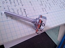
Typical panel mount potentiometer
Drawing of potentiometer with case cut away, showing parts: (A) shaft, (B) stationary carbon composition resistance element, (C) phosphor bronze wiper, (D) shaft attached to wiper, (E, G) terminals connected to ends of resistance element, (F) terminal connected to wiper.
A potentiometer (colloquially, pot) is a three-terminal resistor with a continuously adjustable tapping point controlled by rotation of a shaft or knob or by a linear slider.[23] The name potentiometer comes from its function as an adjustable voltage divider to provide a variable potential at the terminal connected to the tapping point. Volume control in an audio device is a common application of a potentiometer. A typical low power potentiometer (see drawing) is constructed of a flat resistance element (B) of carbon composition, metal film, or conductive plastic, with a springy phosphor bronze wiper contact (C) which moves along the surface. An alternate construction is resistance wire wound on a form, with the wiper sliding axially along the coil.[23] These have lower resolution, since as the wiper moves the resistance changes in steps equal to the resistance of a single turn.[23]
High-resolution multiturn potentiometers are used in precision applications. These have wire-wound resistance elements typically wound on a helical mandrel, with the wiper moving on a helical track as the control is turned, making continuous contact with the wire. Some include a conductive-plastic resistance coating over the wire to improve resolution. These typically offer ten turns of their shafts to cover their full range. They are usually set with dials that include a simple turns counter and a graduated dial, and can typically achieve three-digit resolution. Electronic analog computers used them in quantity for setting coefficients and delayed-sweep oscilloscopes of recent decades included one on their panels.
Resistance decade boxes
A resistance decade box or resistor substitution box is a unit containing resistors of many values, with one or more mechanical switches which allow any one of various discrete resistances offered by the box to be dialed in. Usually the resistance is accurate to high precision, ranging from laboratory/calibration grade accuracy of 20 parts per million, to field grade at 1%. Inexpensive boxes with lesser accuracy are also available. All types offer a convenient way of selecting and quickly changing a resistance in laboratory, experimental and development work without needing to attach resistors one by one, or even stock each value. The range of resistance provided, the maximum resolution, and the accuracy characterize the box. For example, one box offers resistances from 0 to 100 megohms, maximum resolution 0.1 ohm, accuracy 0.1%.[24]
Special devices
There are various devices whose resistance changes with various quantities. The resistance of NTC thermistors exhibit a strong negative temperature coefficient, making them useful for measuring temperatures. Since their resistance can be large until they are allowed to heat up due to the passage of current, they are also commonly used to prevent excessive current surges when equipment is powered on. Similarly, the resistance of a humistor varies with humidity. One sort of photodetector, the photoresistor, has a resistance which varies with illumination.
The strain gauge, invented by Edward E. Simmons and Arthur C. Ruge in 1938, is a type of resistor that changes value with applied strain. A single resistor may be used, or a pair (half bridge), or four resistors connected in a Wheatstone bridge configuration. The strain resistor is bonded with adhesive to an object that is subjected to mechanical strain. With the strain gauge and a filter, amplifier, and analog/digital converter, the strain on an object can be measured.
A related but more recent invention uses a Quantum Tunnelling Composite to sense mechanical stress. It passes a current whose magnitude can vary by a factor of 1012 in response to changes in applied pressure.
Measurement
The value of a resistor can be measured with an ohmmeter, which may be one function of a multimeter. Usually, probes on the ends of test leads connect to the resistor. A simple ohmmeter may apply a voltage from a battery across the unknown resistor (with an internal resistor of a known value in series) producing a current which drives a meter movement. The current, in accordance with Ohm’s law, is inversely proportional to the sum of the internal resistance and the resistor being tested, resulting in an analog meter scale which is very non-linear, calibrated from infinity to 0 ohms. A digital multimeter, using active electronics, may instead pass a specified current through the test resistance. The voltage generated across the test resistance in that case is linearly proportional to its resistance, which is measured and displayed. In either case the low-resistance ranges of the meter pass much more current through the test leads than do high-resistance ranges. This allows for the voltages present to be at reasonable levels (generally below 10 volts) but still measurable.
Measuring low-value resistors, such as fractional-ohm resistors, with acceptable accuracy requires four-terminal connections. One pair of terminals applies a known, calibrated current to the resistor, while the other pair senses the voltage drop across the resistor. Some laboratory quality ohmmeters, milliohmmeters, and even some of the better digital multimeters sense using four input terminals for this purpose, which may be used with special test leads called Kelvin clips. Each of the two clips has a pair of jaws insulated from each other. One side of each clip applies the measuring current, while the other connections are only to sense the voltage drop. The resistance is again calculated using Ohm’s Law as the measured voltage divided by the applied current.
Standards
Production resistors
Resistor characteristics are quantified and reported using various national standards. In the US, MIL-STD-202[25] contains the relevant test methods to which other standards refer.
There are various standards specifying properties of resistors for use in equipment:
- IEC 60062 (IEC 62) / DIN 40825 / BS 1852 / IS 8186 / JIS C 5062 etc. (Resistor color code, RKM code, date code)
- EIA RS-279 / DIN 41429 (Resistor color code)
- IEC 60063 (IEC 63) / JIS C 5063 (Standard E series values)
- MIL-PRF-26
- MIL-PRF-39007 (Fixed power, established reliability)
- MIL-PRF-55342 (Surface-mount thick and thin film)
- MIL-PRF-914
- MIL-R-11 Standard Canceled
- MIL-R-39017 (Fixed, General Purpose, Established Reliability)
- MIL-PRF-32159 (zero ohm jumpers)
- UL 1412 (fusing and temperature limited resistors)[26]
There are other United States military procurement MIL-R- standards.
Resistance standards
The primary standard for resistance, the «mercury ohm» was initially defined in 1884 in as a column of mercury 106.3 cm long and 1 square millimeter in cross-section, at 0 degrees Celsius. Difficulties in precisely measuring the physical constants to replicate this standard result in variations of as much as 30 ppm. From 1900 the mercury ohm was replaced with a precision machined plate of manganin.[27] Since 1990 the international resistance standard has been based on the quantized Hall effect discovered by Klaus von Klitzing, for which he won the Nobel Prize in Physics in 1985.[28]
Resistors of extremely high precision are manufactured for calibration and laboratory use. They may have four terminals, using one pair to carry an operating current and the other pair to measure the voltage drop; this eliminates errors caused by voltage drops across the lead resistances, because no charge flows through voltage sensing leads. It is important in small value resistors (100–0.0001 ohm) where lead resistance is significant or even comparable with respect to resistance standard value.[29]
Resistor marking
Wheel-based RMA Resistor Color Code guide. Circa 1945–1950.
Axial resistors’ cases are usually tan, brown, blue, or green (though other colors are occasionally found as well, such as dark red or dark gray), and display 3–6 colored stripes that indicate resistance (and by extension tolerance), and may include bands to indicate the temperature coefficient and reliability class. In four-striped resistors, the first two stripes represent the first two digits of the resistance in ohms, the third represents a multiplier, and the fourth the tolerance (which if absent, denotes ±20%). For five- and six- striped resistors the third band is the third digit, the fourth is the multiplier and the fifth is the tolerance; a sixth stripe represents the temperature coefficient. The power rating of the resistor is usually not marked and is deduced from its size.
Surface-mount resistors are marked numerically.
Early 20th century resistors, essentially uninsulated, were dipped in paint to cover their entire body for color-coding. This base color represented the first digit. A second color of paint was applied to one end of the element to represent a second digit, and a color dot (or band) in the middle provided the third digit. The rule was «body, tip, dot», providing two significant digits for value and the decimal multiplier, in that sequence. Default tolerance was ±20%. Closer-tolerance resistors had silver (±10%) or gold-colored (±5%) paint on the other end.
Preferred values
Early resistors were made in more or less arbitrary round numbers; a series might have 100, 125, 150, 200, 300, etc.[30] Early power wirewound resistors, such as brown vitreous-enameled types, were made with a system of preferred values like some of those mentioned here. Resistors as manufactured are subject to a certain percentage tolerance, and it makes sense to manufacture values that correlate with the tolerance, so that the actual value of a resistor overlaps slightly with its neighbors. Wider spacing leaves gaps; narrower spacing increases manufacturing and inventory costs to provide resistors that are more or less interchangeable.
A logical scheme is to produce resistors in a range of values which increase in a geometric progression, so that each value is greater than its predecessor by a fixed multiplier or percentage, chosen to match the tolerance of the range. For example, for a tolerance of ±20% it makes sense to have each resistor about 1.5 times its predecessor, covering a decade in 6 values. More precisely, the factor used is 1.4678 ≈ , giving values of 1.47, 2.15, 3.16, 4.64, 6.81, 10 for the 1–10-decade (a decade is a range increasing by a factor of 10; 0.1–1 and 10–100 are other examples); these are rounded in practice to 1.5, 2.2, 3.3, 4.7, 6.8, 10; followed by 15, 22, 33, … and preceded by … 0.47, 0.68, 1. This scheme has been adopted as the E6 series of the IEC 60063 preferred number values. There are also E12, E24, E48, E96 and E192 series for components of progressively finer resolution, with 12, 24, 48, 96, and 192 different values within each decade. The actual values used are in the IEC 60063 lists of preferred numbers.
A resistor of 100 ohms ±20% would be expected to have a value between 80 and 120 ohms; its E6 neighbors are 68 (54–82) and 150 (120–180) ohms. A sensible spacing, E6 is used for ±20% components; E12 for ±10%; E24 for ±5%; E48 for ±2%, E96 for ±1%; E192 for ±0.5% or better. Resistors are manufactured in values from a few milliohms to about a gigaohm in IEC60063 ranges appropriate for their tolerance. Manufacturers may sort resistors into tolerance-classes based on measurement. Accordingly, a selection of 100 ohms resistors with a tolerance of ±10%, might not lie just around 100 ohm (but no more than 10% off) as one would expect (a bell-curve), but rather be in two groups – either between 5 and 10% too high or 5 to 10% too low (but not closer to 100 ohm than that) because any resistors the factory had measured as being less than 5% off would have been marked and sold as resistors with only ±5% tolerance or better. When designing a circuit, this may become a consideration. This process of sorting parts based on post-production measurement is known as «binning», and can be applied to other components than resistors (such as speed grades for CPUs).
SMT resistors
This image shows four surface-mount resistors (the component at the upper left is a capacitor) including two zero-ohm resistors. Zero-ohm links are often used instead of wire links, so that they can be inserted by a resistor-inserting machine. Their resistance is negligible.
Surface mounted resistors of larger sizes (metric 1608 and above) are printed with numerical values in a code related to that used on axial resistors. Standard-tolerance surface-mount technology (SMT) resistors are marked with a three-digit code, in which the first two digits are the first two significant digits of the value and the third digit is the power of ten (the number of zeroes). For example:
- 334 = 33 × 104 Ω = 330 kΩ
- 222 = 22 × 102 Ω = 2.2 kΩ
- 473 = 47 × 103 Ω = 47 kΩ
- 105 = 10 × 105 Ω = 1 MΩ
Resistances less than 100 Ω are written: 100, 220, 470. The final zero represents ten to the power zero, which is 1. For example:
- 100 = 10 × 100 Ω = 10 Ω
- 220 = 22 × 100 Ω = 22 Ω
Sometimes these values are marked as 10 or 22 to prevent a mistake.
Resistances less than 10 Ω have ‘R’ to indicate the position of the decimal point (radix point). For example:
- 4R7 = 4.7 Ω
- R300 = 0.30 Ω
- 0R22 = 0.22 Ω
- 0R01 = 0.01 Ω
000 and 0000 sometimes appear as values on surface-mount zero-ohm links, since these have (approximately) zero resistance.
More recent surface-mount resistors are too small, physically, to permit practical markings to be applied.
Precision resistor markings
Many precision resistors, including surface mount and axial-lead types, are marked with a four-digit code. The first three digits are the significant figures and the fourth is the power of ten. For example:
- 1001 = 100 × 101 Ω = 1.00 kΩ
- 4992 = 499 × 102 Ω = 49.9 kΩ
- 1000 = 100 × 100 Ω = 100 Ω
Axial-lead precision resistors often use color code bands to represent this four-digit code.
EIA-96 marking
The former EIA-96 marking system now included in IEC 60062:2016 is a more compact marking system intended for physically small high-precision resistors. It uses a two-digit code plus a letter (a total of three alphanumeric characters) to indicate 1% resistance values to three significant digits.[31] The two digits (from «01» to «96») are a code that indicates one of the 96 «positions» in the standard E96 series of 1% resistor values. The uppercase letter is a code that indicates a power of ten multiplier. For example, the marking «01C» represents 10 kOhm; «10C» represents 12.4 kOhm; «96C» represents 97.6 kOhm.[32][33][34][35][36]
|
|
Industrial type designation
| Type no. | Power rating (watts) |
MIL-R-11 style |
MIL-R-39008 style |
|---|---|---|---|
| BB | 1⁄8 | RC05 | RCR05 |
| CB | 1⁄4 | RC07 | RCR07 |
| EB | 1⁄2 | RC20 | RCR20 |
| GB | 1 | RC32 | RCR32 |
| HB | 2 | RC42 | RCR42 |
| GM | 3 | — | — |
| HM | 4 | — | — |
| Industrial type designation | Tolerance | MIL designation |
|---|---|---|
| 5 | ±5% | J |
| 2 | ±20% | M |
| 1 | ±10% | K |
| — | ±2% | G |
| — | ±1% | F |
| — | ±0.5% | D |
| — | ±0.25% | C |
| — | ±0.1% | B |
Steps to find out the resistance or capacitance values:[37]
- First two letters gives the power dissipation capacity.
- Next three digits gives the resistance value.
- First two digits are the significant values
- Third digit is the multiplier.
- Final digit gives the tolerance.
If a resistor is coded:
- EB1041: power dissipation capacity = 1/2 watts, resistance value = 10×104±10% = between 9×10⁴ ohms and 11×104 ohms.
- CB3932: power dissipation capacity = 1/4 watts, resistance value = 39×103±20% = between 31.2×10³ and 46.8×10³ ohms.
Electrical and thermal noise
In amplifying faint signals, it is often necessary to minimize electronic noise, particularly in the first stage of amplification. As a dissipative element, even an ideal resistor naturally produces a randomly fluctuating voltage, or noise, across its terminals. This Johnson–Nyquist noise is a fundamental noise source which depends only upon the temperature and resistance of the resistor, and is predicted by the fluctuation–dissipation theorem. Using a larger value of resistance produces a larger voltage noise, whereas a smaller value of resistance generates more current noise, at a given temperature.
The thermal noise of a practical resistor may also be larger than the theoretical prediction and that increase is typically frequency-dependent. Excess noise of a practical resistor is observed only when current flows through it. This is specified in unit of μV/V/decade – μV of noise per volt applied across the resistor per decade of frequency. The μV/V/decade value is frequently given in dB so that a resistor with a noise index of 0 dB exhibits 1 μV (rms) of excess noise for each volt across the resistor in each frequency decade. Excess noise is thus an example of 1/f noise. Thick-film and carbon composition resistors generate more excess noise than other types at low frequencies. Wire-wound and thin-film resistors are often used for their better noise characteristics. Carbon composition resistors can exhibit a noise index of 0 dB while bulk metal foil resistors may have a noise index of −40 dB, usually making the excess noise of metal foil resistors insignificant.[38] Thin film surface mount resistors typically have lower noise and better thermal stability than thick film surface mount resistors. Excess noise is also size-dependent: in general, excess noise is reduced as the physical size of a resistor is increased (or multiple resistors are used in parallel), as the independently fluctuating resistances of smaller components tend to average out.
While not an example of «noise» per se, a resistor may act as a thermocouple, producing a small DC voltage differential across it due to the thermoelectric effect if its ends are at different temperatures. This induced DC voltage can degrade the precision of instrumentation amplifiers in particular. Such voltages appear in the junctions of the resistor leads with the circuit board and with the resistor body. Common metal film resistors show such an effect at a magnitude of about 20 μV/°C. Some carbon composition resistors can exhibit thermoelectric offsets as high as 400 μV/°C, whereas specially constructed resistors can reduce this number to 0.05 μV/°C. In applications where the thermoelectric effect may become important, care has to be taken to mount the resistors horizontally to avoid temperature gradients and to mind the air flow over the board.[39]
Failure modes
The failure rate of resistors in a properly designed circuit is low compared to other electronic components such as semiconductors and electrolytic capacitors. Damage to resistors most often occurs due to overheating when the average power delivered to it greatly exceeds its ability to dissipate heat (specified by the resistor’s power rating). This may be due to a fault external to the circuit but is frequently caused by the failure of another component (such as a transistor that shorts out) in the circuit connected to the resistor. Operating a resistor too close to its power rating can limit the resistor’s lifespan or cause a significant change in its resistance. A safe design generally uses overrated resistors in power applications to avoid this danger.
Low-power thin-film resistors can be damaged by long-term high-voltage stress, even below maximum specified voltage and below maximum power rating. This is often the case for the startup resistors feeding a switched-mode power supply integrated circuit.[citation needed]
When overheated, carbon-film resistors may decrease or increase in resistance.[40]
Carbon film and composition resistors can fail (open circuit) if running close to their maximum dissipation. This is also possible but less likely with metal film and wirewound resistors.
There can also be failure of resistors due to mechanical stress and adverse environmental factors including humidity. If not enclosed, wirewound resistors can corrode.
Surface mount resistors have been known to fail due to the ingress of sulfur into the internal makeup of the resistor. This sulfur chemically reacts with the silver layer to produce non-conductive silver sulfide. The resistor’s impedance goes to infinity. Sulfur resistant and anti-corrosive resistors are sold into automotive, industrial, and military applications. ASTM B809 is an industry standard that tests a part’s susceptibility to sulfur.
An alternative failure mode can be encountered where large value resistors are used (hundreds of kilohms and higher). Resistors are not only specified with a maximum power dissipation, but also for a maximum voltage drop. Exceeding this voltage causes the resistor to degrade slowly reducing in resistance. The voltage dropped across large value resistors can be exceeded before the power dissipation reaches its limiting value. Since the maximum voltage specified for commonly encountered resistors is a few hundred volts, this is a problem only in applications where these voltages are encountered.
Variable resistors can also degrade in a different manner, typically involving poor contact between the wiper and the body of the resistance. This may be due to dirt or corrosion and is typically perceived as «crackling» as the contact resistance fluctuates; this is especially noticed as the device is adjusted. This is similar to crackling caused by poor contact in switches, and like switches, potentiometers are to some extent self-cleaning: running the wiper across the resistance may improve the contact. Potentiometers which are seldom adjusted, especially in dirty or harsh environments, are most likely to develop this problem. When self-cleaning of the contact is insufficient, improvement can usually be obtained through the use of contact cleaner (also known as «tuner cleaner») spray. The crackling noise associated with turning the shaft of a dirty potentiometer in an audio circuit (such as the volume control) is greatly accentuated when an undesired DC voltage is present, often indicating the failure of a DC blocking capacitor in the circuit.
See also
- Circuit design
- Dummy load
- Electrical impedance
- High value resistors (electronics)
- Iron-hydrogen resistor
- Piezoresistive effect
- Shot noise
- Thermistor
- Trimmer (electronics)
References
- ^ Harder, Douglas Wilhelm. «Resistors: A Motor with a Constant Force (Force Source)». Department of Electrical and Computer Engineering, University of Waterloo. Retrieved 9 November 2014.
- ^ American Radio Relay League (ARRL) (2021). «Fundamental Theory—Circuits and Components». ARRL Handbook for Radio Communications (98 ed.). American Radio Relay League. ISBN 978-1-62595-139-7.
- ^ a b c Doug DeMaw, ed. (1968). «Electrical Laws and Circuits —Resistance». Radio Amateurs Handbook (45 ed.). American Radio Relay League.
- ^ Farago, P.S. (1961) An Introduction to Linear Network Analysis, pp. 18–21, The English Universities Press Ltd.
- ^ Wu, F. Y. (2004). «Theory of resistor networks: The two-point resistance». Journal of Physics A: Mathematical and General. 37 (26): 6653–6673. arXiv:math-ph/0402038. Bibcode:2004JPhA…37.6653W. doi:10.1088/0305-4470/37/26/004. S2CID 119611570.
- ^ Wu, Fa Yueh; Yang, Chen Ning (2009). Exactly Solved Models: A Journey in Statistical Mechanics : Selected Papers with Commentaries (1963–2008). World Scientific. pp. 489–. ISBN 978-981-281-388-6.
- ^ «Specifications and How to Interpret Them» (PDF). Stackpole Electronics. Retrieved July 6, 2021.
- ^ https://nl.farnell.com/te-connectivity/rgp0207chj100m/res-100m-5-250mw-axial-thick-film/dp/2805251[bare URL]
- ^ A family of resistors may also be characterized according to its critical resistance. Applying a constant voltage across resistors in that family below the critical resistance will exceed the maximum power rating first; resistances larger than the critical resistance fail first from exceeding the maximum voltage rating. See Middleton, Wendy; Van Valkenburg, Mac E. (2002). Reference data for engineers: radio, electronics, computer, and communications (9 ed.). Newnes. pp. 5–10. ISBN 0-7506-7291-9.
- ^ Harter, James H. and Lin, Paul Y. (1982) Essentials of electric circuits. Reston Publishing Company. pp. 96–97. ISBN 0-8359-1767-3.
- ^ HVR International (ed.). «SR Series: Surge Resistors for PCB Mounting». (PDF; 252 kB), 26 May 2005, retrieved 24 January 2017.
- ^ a b c d e f g Beyschlag, Vishay (2008). «Basics of Linear Fixed Resistors Application Note», Document Number 28771.
- ^ Morris, C. G. (ed.) (1992). Academic Press Dictionary of Science and Technology. Gulf Professional Publishing. p. 360. ISBN 0122004000.
- ^ Principles of automotive vehicles. United States Department of the Army (1985). p. 13
- ^ «Carbon Film Resistor». The Resistorguide. Retrieved 10 March 2013.
- ^ «Thick Film and Thin Film» (PDF). Digi-Key (SEI). Archived from the original (PDF) on 27 September 2011. Retrieved 23 July 2011.
- ^ «Thin and Thick film». resisitorguide.com. resistor guide. Retrieved 3 December 2017.
- ^ Kuhn, Kenneth A. «Measuring the Temperature Coefficient of a Resistor» (PDF). Archived from the original (PDF) on 2016-03-04. Retrieved 2010-03-18.
- ^ Zandman, F.; Stein, S. (1964). «A New Precision Film Resistor Exhibiting Bulk Properties». IEEE Transactions on Component Parts. 11 (2): 107–119. doi:10.1109/TCP.1964.1135008.
- ^ Procedures in Experimental Physics, John Strong, p. 546.
- ^ «Alpha Electronics Corp. Metal Foil Resistors». Alpha-elec.co.jp. Retrieved 2008-09-22.
- ^ «Grid Resistors: High Power/High Current». Milwaukee Resistor Corporation. Retrieved 14 May 2012.
- ^ a b c Mazda, F. F. (1981). Discrete Electronic Components. CUP Archive. pp. 57–61. ISBN 0521234700.
- ^ «Decade Box – Resistance Decade Boxes». Ietlabs.com. Retrieved 2008-09-22.
- ^ «Test method standard: electronic and electrical component parts» (PDF). Department of Defense. Archived from the original (PDF) on 2015-02-09.
- ^ Fusing Resistors and Temperature-Limited Resistors for Radio- and Television- Type Appliances UL 1412. ulstandardsinfonet.ul.com
- ^ Stability of Double-Walled Manganin Resistors Archived 2006-10-06 at the Wayback Machine. NIST.gov
- ^ Klaus von Klitzing The Quantized Hall Effect. Nobel lecture, December 9, 1985. nobelprize.org
- ^ «Standard Resistance Unit Type 4737B». Tinsley.co.uk. Archived from the original on 2008-08-21. Retrieved 2008-09-22.
- ^ «1940 Catalog – page 60 – Resistors». RadioShack. Archived from the original on 11 July 2017. Retrieved 11 July 2017.
- ^ «Chapter 2 — Resistor standards and codes».
- ^ «CRP0603 Series — Precision Chip Resistors». p. 3.
- ^ «Online calculator — EIA-96 SMD resistor».
- ^ «SMD Resistor Codes: How to Find the Value of SMD Resistors».
- ^ «Marking Codes used on Welwyn Chip Resistors». p. 2.
- ^ «Surface Mount Resistor: codes & markings».
- ^ Maini, A. K. (2008), Electronics and Communications Simplified, 9th ed., Khanna Publications. ISBN 817409217X
- ^ Audio Noise Reduction Through the Use of Bulk Metal Foil Resistors – «Hear the Difference» (PDF). Archived from the original (PDF) on 2013-01-19. Retrieved 2009-08-03., Application note AN0003, Vishay Intertechnology Inc, 12 July 2005.
- ^ Jung, Walt (2005). «Chapter 7 – Hardware and Housekeeping Techniques» (PDF). Op Amp Applications Handbook. p. 7.11. ISBN 0-7506-7844-5.
- ^ «Electronic components – resistors». Inspector’s Technical Guide. US Food and Drug Administration. 1978-01-16. Archived from the original on 2008-04-03. Retrieved 2008-06-11.
External links
![]()
Look up resistor in Wiktionary, the free dictionary.
- 4-terminal resistors – How ultra-precise resistors work
- Beginner’s guide to potentiometers, including description of different tapers
- Color Coded Resistance Calculator – archived with WayBack Machine
- Resistor Types – Does It Matter?
- Standard Resistors & Capacitor Values That Industry Manufactures
- Ask The Applications Engineer – Difference between types of resistors
- Resistors and their uses
резистор
- резистор
-
рез’истор, -а
Русский орфографический словарь. / Российская академия наук. Ин-т рус. яз. им. В. В. Виноградова. — М.: «Азбуковник».
.
1999.
Синонимы:
Смотреть что такое «резистор» в других словарях:
-
РЕЗИСТОР — (от латинского resisto сопротивляюсь), устройство на основе проводника с нормированным постоянным (постоянный резистор) или регулируемым (переменный резистор) активным сопротивлением, используемое в электрических цепях для обеспечения требуемого… … Современная энциклопедия
-
Резистор — (от латинского resisto сопротивляюсь), устройство на основе проводника с нормированным постоянным (постоянный резистор) или регулируемым (переменный резистор) активным сопротивлением, используемое в электрических цепях для обеспечения требуемого… … Иллюстрированный энциклопедический словарь
-
РЕЗИСТОР — (англ. resistor от лат. resisto сопротивляюсь), радио или электротехническое изделие, основное функциональное назначение которого оказывать известное активное сопротивление электрическому току. Резистор характеризуют номинальным значением… … Большой Энциклопедический словарь
-
резистор — резистер, варистор Словарь русских синонимов. резистор сущ., кол во синонимов: 7 • варистор (2) • … Словарь синонимов
-
резистор — Элемент электрической цепи, предназначенный для использования его электрического сопротивления. [ГОСТ Р 52002 2003] омическое сопротивление резистор [IEV number 151 13 19] EN resistor two terminal device characterized essentially by its… … Справочник технического переводчика
-
РЕЗИСТОР — (сопротивление), компонент электрической цепи или ЭЛЕКТРОННОЙ СХЕМЫ, обладающий определенным номинальным (известным) СОПРОТИВЛЕНИЕМ электрическому току. Резисторы ограничивают силу тока, текущего в цепи. Резисторы в электронных схемах обычно… … Научно-технический энциклопедический словарь
-
РЕЗИСТОР F1 — см. Рекомендуется для использования в свежем виде. Раннеспелый. Период от массовых всходов до начала технической спелости 90 100 дней. Растение низкорослое. Лист среднего размера, зеленый, слабопузырчатый, восковой налет слабый. Кочан округлый,… … Энциклопедия семян. Овощные культуры
-
РЕЗИСТОР — радио или электротехническое изделие, обладающее только активным электрическим сопротивлением и определяющее в цепи силу тока и напряжение. Различают Р.: проволочные и непроволочные, постоянного и переменного сопротивлений класса точности от… … Большая политехническая энциклопедия
-
Резистор — Иное название этого понятия «Сопротивление»; см. также другие значения. Шесть резисторов разных номиналов и точности, промаркированные с помощью цветовой схемы Резистор … Википедия
-
резистор — а; м. [англ. resistor] Радио или электротехническая деталь, создающая сопротивление в электрической цепи. * * * резистор (англ. resistor, от лат. resisto сопротивляюсь), радио или электротехническое изделие, основное функциональное назначение… … Энциклопедический словарь
-
Резистор — 1 . Резистор D. Widerstand E. Resistor F. Résistance По ГОСТ 19880 74* Источник: ГОСТ 21414 75: Резисторы. Термины и определения оригинал документа … Словарь-справочник терминов нормативно-технической документации
резистор
→
резистор — существительное, именительный п., муж. p., ед. ч.
↳
резистор — существительное, винительный п., муж. p., ед. ч.
Часть речи: существительное
| Единственное число | Множественное число | |
|---|---|---|
| Им. |
резистор |
резисторы |
| Рд. |
резистора |
резисторов |
| Дт. |
резистору |
резисторам |
| Вн. |
резистор |
резисторы |
| Тв. |
резистором |
резисторами |
| Пр. |
резисторе |
резисторах |
Если вы нашли ошибку, пожалуйста, выделите фрагмент текста и нажмите Ctrl+Enter.
Что такое резистор
Резистор — это самый распространенный радиоэлемент, который используется в электронике. Я могу со 100% уверенностью сказать, что абсолютно на любой плате какого-либо устройства вы найдете хотя бы один резистор. Резистор имеет важное свойство — он обладает активным сопротивлением электрическому току. Существует также и реактивное сопротивление. Подробнее про реактивное и активное сопротивление.
Виды резисторов
Существует множество видов резисторов, которые используются в радио-электронной промышленности. Давайте разберем основные из них.
Постоянные резисторы
Постоянное резисторы выглядят примерно вот так:
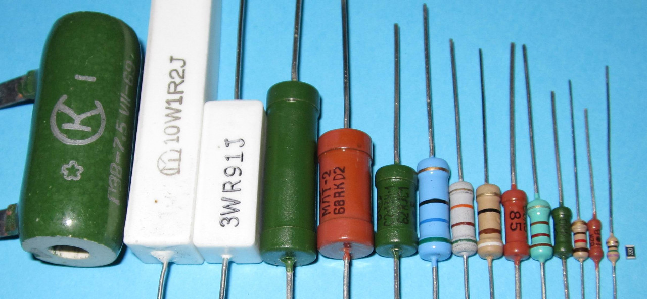
Слева мы видим большой зеленый резистор, который рассеивает очень большую мощность. Справа — маленький крохотный SMD резистор, который рассеивает очень маленькую мощность, но при этом отлично выполняет свою функцию. Про то, как определить сопротивление резистора, можно прочитать в статье маркировка резисторов.
Вот так выглядит постоянный резистор на электрических схемах:


Наше отечественное изображение резистора изображают прямоугольником (слева), а заморский вариант (справа), или как говорят — буржуйский, используется в иностранных радиосхемах.
Вот так маркируются мощности на советских резисторах:

Далее мощность маркируется с помощью римских цифр. V — 5 Ватт, X — 10 Ватт, L -50 Ватт и тд.
Какие еще бывают виды резисторов? Давайте рассмотрим самые распространенные:
20 ваттный стекловидный с проволочными выводами, 20 ваттный с монтажными лепестками,30 ваттный в стекловидной эмали, 5 ваттный и 20 ваттный с монтажными лепестками

1, 3, 5 ваттные керамические; 5,10,25, 50 ваттные с кондуктивным теплообменом

2, 1, 0.5, 0.25, 0.125 ваттные углеродной структуры; SMD резисторы типоразмеров 2010, 1206, 0805, 0603,0402; резисторная SMD сборка, 6,8,10 выводные резисторные сборки для сквозного монтажа, резистор в DIP корпусе

Переменные резисторы
Переменные резисторы выглядят так:

На схемах обозначаются так:

Соответственно отечественный и зарубежный вариант.
А вот и их цоколевка (расположение выводов):


Переменный резистор, который управляет напряжением называется потенциометром, а который управляет силой тока — реостатом. Здесь заложен принцип делителя напряжения и делителя тока соответственно. Различие между потенциометром и реостатом в схеме подключения самого переменного резистора. В схеме с реостатом в переменном резисторе соединяется средний и крайний выводы.
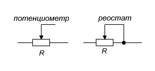
Переменные резисторы, у которых сопротивление можно менять только при помощи отвертки или шестигранного ключика, называются подстроечными переменными резисторами. У них есть специальные пазы для регулировки сопротивления (отмечены красной рамкой):

А вот так обозначаются подстроечные резисторы и их схемы включения в режиме реостата и потенциометра.

Термисторы
Термисторы — это резисторы на основе полупроводниковых материалов. Их сопротивление резко зависит от температуры окружающей среды. Есть такой важный параметр термисторов, как ТКС — тепловой коэффициент сопротивления. Грубо говоря, этот коэффициент показывает на сколько изменится сопротивление термистора при изменении температуры окружающей среды.
Этот коэффициент может быть как отрицательный, так и положительный. Если ТКС отрицательный, то такой термистор называют термистором, а если ТКС положительный, то такой термистор называют позистором. У термисторов при увеличении температуры окружающей среды сопротивление падает. У позисторов с увеличением температуры окружающей среды растет и сопротивление.

Так как термисторы обладают отрицательным коэффициентом (NTC — Negative Temperature Coefficient — отрицательный ТКС), а позисторы положительным коэффициентом (РТС — Positive Temperature Coefficient — положительный ТКС), то и на схемах они будут обозначаться соответствующим образом.

Варисторы
Есть также особый класс резисторов, которые резко изменяют свое сопротивление при увеличении напряжения — это варисторы.

Это свойство варисторов широко используют от защиты перенапряжений в цепи, а также от импульсных скачков напряжения. Допустим у нас «скакануло» напряжение. Все это дело «чухнул» варистор и сразу же резко изменил сопротивление в меньшую сторону. Так как сопротивление варистора стало очень маленьким, то весь электрический ток сразу же начнет протекать через него, тем самым защищая основную цепь радиоэлектронного устройства. При этом варистор берет всю мощность импульса на себя и очень часто платит за это своей жизнью, то его выгорает наглухо

На схемах варисторы обозначаются вот таким образом:

Фоторезисторы
Большой популярностью также пользуются фоторезисторы. Они изменяют свое сопротивление, если на них посветить. В этих целях можно применять как солнечный свет, так и искусственный, например, от фонарика.

На схемах они обозначаются вот таким образом:

Тензорезисторы
Принцип действия их работы основан на растяжении тонких печатных проводников. При растяжении они становятся еще тоньше. Это все равно, что вытягивать жевательную резинку. Чем больше вы ее вытягиваете, тем тоньше она становится. А как вы знаете, чем тоньше проводник, тем бОльшим сопротивлением он обладает.

На схемах тензорезистор выглядит вот так:
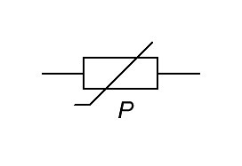
Вот анимация работы тензорезистора, позаимствованная с Википедии.

Ну и как вы догадались, тензорезисторы используются в электронных весах, а также в различных датчиках, где применяется какое-либо давление, либо сила.
Как измерить сопротивление резистора
Любой резистор обладает сопротивлением. Кто не в курсе, что такое сопротивление и как оно измеряется, в срочном порядке читаем эту статью. Сопротивление измеряется в Омах. Но как же нам узнать сопротивление резистора? Есть прямой и косвенный методы.
Прямой метод он самый простой. Нам нужно взять мультиметр и просто замерять сопротивление резистора. Давайте рассмотрим, как все это выглядит. Я беру мультиметр, выставляю крутилку на измерение сопротивления и цепляюсь к выводам резистора.

Резистор я брал на 1 кОм. Он мне показал 976 Ом, что в принципе тоже нормально, так как у таких резисторов всегда существует некая погрешность.
Косвенный метод измерения заключается в том, что мы будем рассчитывать сопротивление резистора через закон Ома.
Поэтому, чтобы узнать сопротивление резистора, нам надо напряжение на концах резистора поделить на силу тока, которая течет через резистор. Все довольно просто!
Допустим, я хочу узнать сопротивление нити накала лампочки, когда она источает свет. Думаю, некоторые из вас в курсе, что сопротивление холодной вольфрамовой нити и раскаленной — это абсолютно разные сопротивления. Я ведь не смогу измерить мультиметром в режиме измерения сопротивления раскаленную вольфрамовую нить лампы накаливания, так ведь? Поэтому, нам как нельзя кстати подойдет эта формула
Давайте же узнаем это на опыте. У меня есть лабораторный блок питания, который показывает сразу напряжение и силу тока, которая течет через нагрузку. Беру лампу, выставляю на блоке питания напряжение, которое написано на самой лампе и подключаю ее к клеммам блока питания.

Итак, получается, что на выводах лампы сейчас напряжение 12 Вольт, а ток, который течет в цепи, а следовательно и через лампу 0,71 Ампер.
Получаем, что сопротивление раскаленной нити лампы в данном случае составляет

Последовательное и параллельное соединение резисторов
Все вышеописанные резисторы можно соединять параллельно или последовательно. При параллельном соединении выводы резисторов соединятся в общих точках.

В этом случае, чтобы узнать общее сопротивление всех резисторов в цепи, достаточно будет воспользоваться формулой, где сопротивление между точками А и В (RAB) и есть то самое R общее:

При последовательном соединении номиналы резисторов просто тупо суммируются

В этом случае
![]()
Хорошее видео по теме
Используйте калькулятор цветовой маркировки резисторов.
Похожие статьи по теме «резисторы»
Маркировка резисторов
Фоторезистор
RC цепь
Активное и реактивное сопротивление
Что такое сопротивление
Закон Ома
Содержание
- 1 Цифро-буквенная маркировка резисторов
- 1.1
Примеры цифро-буквенной маркировки резисторов
- 1.1
- 2 Цветовая маркировка резисторов
- 3 Маркировка SMD резисторов
- 4 Таблица кодов SMD резисторов и их значений
- 5 Маркировка SMD резисторов по EIA-96
- 5.1 Таблица маркировки резисторов по по EIA-96 (коды номиналов)
- 5.2 Таблица маркировки резисторов по по EIA-96 (множитель)
Визуально определить значение сопротивления резистора не представляется возможным. Ввиду очень малых размеров резисторов, полностью написать их номинал на корпус не предоставляется возможным. Поэтому и применяют маркировку резисторов, которая бывает кодовой, и цветовой, цифро-буквенной.
Цифро-буквенная маркировка резисторов
Самым простым в части оценки является советский резистор, номинал его мощности наносится прямо на корпусе маркировкой МЛТ-1 и так далее, где единица измерения – это мощность, а МЛТ – это вид наиболее ходовые в свое советское время резисторы а эта сокращение означает что резистор М- металлопленочный, Л- лакированный, Т-термоустойчивый. Мощность таких резисторов зависит от их размеров, чем больше размеры резистора – тем большую мощности он способен рассеять. Эти резисторы уже вымирающий вид, найти их можно в старой радиоэлектронной технике.

Для резисторов МЛТ типа единицей измерения сопротивления как и у других выступают Омы, обозначаются они как R и E. Точный размер мощности обозначает дополнительной буквой «К» – килоомы или буквой «М» — мегаомы, система измерения здесь достаточно проста. Например: 33E – это 33 Ома, а 47К – это 47 кОм, соответственно 1М2 – 1.2 Мегаом и так далее.
Если стоит только цифра без буквы, то они означают что это сопротивление в Ом, а допуск при таком обозначении равен 20%. К примеру если написано число 10, значит перед вами резистор с сопротивлением на 10 Ом ,а допуск равен 20%.


Примеры цифро-буквенной маркировки резисторов

3E9И или 3R9 означает что сопротивления 3,9 Ом, допуск 5%
2К2И означает что сопротивления 2,2 кОм,допуск 5%
5К1С означает что сопротивления 5,1 кОм,допуск 10%
Цветовая маркировка резисторов
Цветовая маркировка немного упростила процесс маркировки в масштабах массового производства, но также и запутала некоторых радиолюбителей, но на самом деле все просто.
Стартовой точкой отчета принято считать золотую полоску или же серебряную – это начальное звено, и оно не считается, необходимо повернуть сориентировать таким образом, чтобы цветные полоски начинались с левой стороны.
Далее считывает номер по полоскам:
-
- 0-черный;
- 1-коричневый ;
- 2-Красный ;
- 3-Оранжевый ;
- 4-Желтый ;
- 5-Зеленый ;
- 6-Синий ;
- 7-Фиолетовый ;
- 8-Серый ;
- 9-Белый.
Третья полоса в штрих коде имеет немного иное значение – она отмеряет количество нулей, которые необходимо добавить к полученному значению. Следовательно, черный – 0, коричный – 1 ноль (0), красный – 2 нуля (00) и так далее.

Чтобы упростить себе подсчеты можно воспользоваться программой на компьютере которая называется Резистор 2.2 (ссылка на скачивание программы во вложении). Она упростит подсчеты и автоматически покажет мощность резистора при вводе всех полосок. Либо же воспользоваться калькулятором цветовой маркировки резистора прямо онлайн.
Маркировка SMD резисторов
С маркировкой SMD немного сложнее, размеры SMD резисторов не позволяют нанести на них цветовые кольца либо написать номинал. Поэтому маркируются они 3 или 4 цифрами, кроме резисторов типоразмера 0402. Значения резисторов типа 0402 можно найти в таблице. Остальные имеют следующий порядок маркировки.
Резисторы с допуском до 10 % имеют в маркировке 3 цифры, где первые 2 цифры – это номинал резистора, а последняя – обозначает десятичное значение.
Пример маркировки SMD резисторов:
Резистор с 3 символами
Резистор с цифрами 222 – означает 22 * 102 = 2200 Ом или другими словами 2,2 кОм.
Резистор с 4 символами
Резисторы с 4 символами имеют допуск 1 %, подсчет проводим аналогичным образом: 4422 это 442*2 * 102 = 44,2 кОм

Бывают также smd резистор без маркировки, таких резисторов сопротивление равно 0, нужны они просто чтобы заполнить пустое пространство в плате, их еще называют нулевыми резисторами.
Использованием кодов в настоящее время – самый популярный способ маркировки SMD резисторов, основанный на табличных кодах каждого показателя.
Таблица кодов SMD резисторов и их значений
| Код smd | Значение | Код smd | Значение | Код smd | Значение | Код smd | Значение |
|---|---|---|---|---|---|---|---|
| R10 | 0.1 Ом | 1R0 | 1 Ом | 100 | 10 Ом | 101 | 100 Ом |
| R11 | 0.11 Ом | 1R1 | 1.1 Ом | 110 | 11 Ом | 111 | 110 Ом |
| R12 | 0.12 Ом | 1R2 | 1.2 Ом | 120 | 12 Ом | 121 | 120 Ом |
| R13 | 0.13 Ом | 1R3 | 1.3 Ом | 130 | 13 Ом | 131 | 130 Ом |
| R15 | 0.15 Ом | 1R5 | 1.5 Ом | 150 | 15 Ом | 151 | 150 Ом |
| R16 | 0.16 Ом | 1R6 | 1.6 Ом | 160 | 16 Ом | 161 | 160 Ом |
| R18 | 0.18 Ом | 1R8 | 1.8 Ом | 180 | 18 Ом | 181 | 180 Ом |
| R20 | 0.2 Ом | 2R0 | 2 Ом | 200 | 20 Ом | 201 | 200 Ом |
| R22 | 0.22 Ом | 2R2 | 2.2 Ом | 220 | 22 Ом | 221 | 220 Ом |
| R24 | 0.24 Ом | 2R4 | 2.4 Ом | 240 | 24 Ом | 241 | 240 Ом |
| R27 | 0.27 Ом | 2R7 | 2.7 Ом | 270 | 27 Ом | 271 | 270 Ом |
| R30 | 0.3 Ом | 3R0 | 3 Ом | 300 | 30 Ом | 301 | 300 Ом |
| R33 | 0.33 Ом | 3R3 | 3.3 Ом | 330 | 33 Ом | 331 | 330 Ом |
| R36 | 0.36 Ом | 3R6 | 3.6 Ом | 360 | 36 Ом | 361 | 360 Ом |
| R39 | 0.39 Ом | 3R9 | 3.9 Ом | 390 | 39 Ом | 391 | 390 Ом |
| R43 | 0.43 Ом | 4R3 | 4.3 Ом | 430 | 43 Ом | 431 | 430 Ом |
| R47 | 0.47 Ом | 4R7 | 4.7 Ом | 470 | 47 Ом | 471 | 470 Ом |
| R51 | 0.51 Ом | 5R1 | 5.1 Ом | 510 | 51 Ом | 511 | 510 Ом |
| R56 | 0.56 Ом | 5R6 | 5.6 Ом | 560 | 56 Ом | 561 | 560 Ом |
| R62 | 0.62 Ом | 6R2 | 6.2 Ом | 620 | 62 Ом | 621 | 620 Ом |
| R68 | 0.68 Ом | 6R8 | 6.8 Ом | 680 | 68 Ом | 681 | 680 Ом |
| R75 | 0.75 Ом | 7R5 | 7.5 Ом | 750 | 75 Ом | 751 | 750 Ом |
| R82 | 0.82 Ом | 8R2 | 8.2 Ом | 820 | 82 Ом | 821 | 820 Ом |
| R91 | 0.91 Ом | 9R1 | 9.1 Ом | 910 | 91 Ом | 911 | 910 Ом |
| Код smd | Значение | Код smd | Значение | Код smd | Значение | Код smd | Значение |
|---|---|---|---|---|---|---|---|
| 102 | 1 кОм | 103 | 10 кОм | 104 | 100 кОм | 105 | 1 МОм |
| 112 | 1.1 кОм | 113 | 11 кОм | 114 | 110 кОм | 115 | 1.1 МОм |
| 122 | 1.2 кОм | 123 | 12 кОм | 124 | 120 кОм | 125 | 1.2 МОм |
| 132 | 1.3 кОм | 133 | 13 кОм | 134 | 130 кОм | 135 | 1.3 МОм |
| 152 | 1.5 кОм | 153 | 15 кОм | 154 | 150 кОм | 155 | 1.5 МОм |
| 162 | 1.6 кОм | 163 | 16 кОм | 164 | 160 кОм | 165 | 1.6 МОм |
| 182 | 1.8 кОм | 183 | 18 кОм | 184 | 180 кОм | 185 | 1.8 МОм |
| 202 | 2 кОм | 203 | 20 кОм | 204 | 200 кОм | 205 | 2 МОм |
| 222 | 2.2 кОм | 223 | 22 кОм | 224 | 220 кОм | 225 | 2.2 МОм |
| 242 | 2.4 кОм | 243 | 24 кОм | 244 | 240 кОм | 245 | 2.4 МОм |
| 272 | 2.7 кОм | 273 | 27 кОм | 274 | 270 кОм | 275 | 2.7 МОм |
| 302 | 3 кОм | 303 | 30 кОм | 304 | 300 кОм | 305 | 3 МОм |
| 332 | 3.3 кОм | 333 | 33 кОм | 334 | 330 кОм | 335 | 3.3 МОм |
| 362 | 3.6 кОм | 363 | 36 кОм | 364 | 360 кОм | 365 | 3.6 МОм |
| 392 | 3.9 кОм | 393 | 39 кОм | 394 | 390 кОм | 395 | 3.9 МОм |
| 432 | 4.3 кОм | 433 | 43 кОм | 434 | 430 кОм | 435 | 4.3 МОм |
| 472 | 4.7 кОм | 473 | 47 кОм | 474 | 470 кОм | 475 | 4.7 МОм |
| 512 | 5.1 кОм | 513 | 51 кОм | 514 | 510 кОм | 515 | 5.1 МОм |
| 562 | 5.6 кОм | 563 | 56 кОм | 564 | 560 кОм | 565 | 5.6 МОм |
| 622 | 6.2 кОм | 623 | 62 кОм | 624 | 620 кОм | 625 | 6.2 МОм |
| 682 | 6.8 кОм | 683 | 68 кОм | 684 | 680 кОм | 685 | 6.8 МОм |
| 752 | 7.5 кОм | 753 | 75 кОм | 754 | 750 кОм | 755 | 7.5 МОм |
| 822 | 8.2 кОм | 823 | 82 кОм | 824 | 820 кОм | 815 | 8.2 МОм |
| 912 | 9.1 кОм | 913 | 91 кОм | 914 | 910 кОм | 915 | 9.1 МОм |
Маркировка SMD резисторов по EIA-96
SMD резисторы с более большей точностью и более малыми размерами привели к созданию компактной маркировке. Был придуман стандарт EIA-96. Этот стандарт создан для резисторов с допуском по сопротивлению в 1%.

Эта система маркировки состоит из трех символов: две первые цифры это код номинала резистора, а следующий за ними символ это множитель. Берем SMD резистор смотрим первые 2 цифры и находим соответствующее сопротивление по таблице, далее смотрим на цифру и также по таблице смотри множитель на который на нужно умножиться. Все довольно просто.
Таблица маркировки резисторов по по EIA-96 (коды номиналов)
| Код | Число | Код | Число | Код | Число | Число | Число |
|---|---|---|---|---|---|---|---|
| 01 | 100 | 25 | 178 | 49 | 316 | 73 | 562 |
| 02 | 102 | 26 | 182 | 50 | 324 | 74 | 576 |
| 03 | 105 | 27 | 187 | 51 | 332 | 75 | 590 |
| 04 | 107 | 28 | 191 | 52 | 340 | 76 | 604 |
| 05 | 110 | 29 | 196 | 53 | 348 | 77 | 619 |
| 06 | 113 | 30 | 200 | 54 | 357 | 78 | 634 |
| 07 | 115 | 31 | 205 | 55 | 365 | 79 | 649 |
| 08 | 118 | 32 | 210 | 56 | 374 | 80 | 665 |
| 09 | 121 | 33 | 215 | 57 | 383 | 81 | 681 |
| 10 | 124 | 34 | 221 | 58 | 392 | 82 | 698 |
| 11 | 127 | 35 | 226 | 59 | 402 | 83 | 715 |
| 12 | 130 | 36 | 232 | 60 | 412 | 84 | 732 |
| 13 | 133 | 37 | 237 | 61 | 422 | 85 | 750 |
| 14 | 137 | 38 | 243 | 62 | 432 | 86 | 768 |
| 15 | 140 | 39 | 249 | 63 | 442 | 87 | 787 |
| 16 | 143 | 40 | 255 | 64 | 453 | 88 | 806 |
| 17 | 147 | 41 | 261 | 65 | 464 | 89 | 825 |
| 18 | 150 | 42 | 267 | 66 | 475 | 90 | 845 |
| 19 | 154 | 43 | 274 | 67 | 487 | 91 | 866 |
| 20 | 158 | 44 | 280 | 68 | 499 | 92 | 887 |
| 21 | 162 | 45 | 287 | 69 | 511 | 93 | 909 |
| 22 | 165 | 46 | 294 | 70 | 523 | 94 | 931 |
| 23 | 169 | 47 | 301 | 71 | 536 | 95 | 953 |
| 24 | 174 | 48 | 309 | 72 | 549 | 96 | 976 |
Таблица маркировки резисторов по по EIA-96 (множитель)
| Код | Множитель |
|---|---|
| Z | 0.001 |
| Y or R | 0.01 |
| X or S | 0.1 |
| A | 1 |
| B or H | 10 |
| C | 100 |
| D | 1000 |
| E | 10000 |
| F | 100000 |
При передаче электрического тока на расстояние из-за сопротивления проводов теряется часть энергии. В таких случаях сопротивление является негативным фактором и его стараются свести к минимуму.
Другое дело электрические цепи в электронных устройствах. Там резистор выполняет много полезных функций. В электронных схемах используется свойства этих пассивных компонентов для ограничения тока в многочисленных цепях. С их помощью обеспечивается нужный режим работы усилительных каскадов.
Что такое резистор?
Название этого электронного элемента произошло от латинского слова resisto — сопротивляюсь. То есть – это пассивный элемент
применяемый в электрических цепях, действие которого основано на сопротивлении току. Основной характеристикой этого электронного компонента является величина его электрического сопротивления.
Пассивность данного электронного компонента означает то, что основной его функцией является поглощение электрической энергии. В отличие от активных элементов электроники, он ничего не генерирует, а только пассивно рассеивает электричество, преобразуя его в тепло. В схемах замещения сопротивление является основным параметром, в то время как ёмкость и индуктивность – паразитные величины.
Применение
Резисторы применяются во всех электрических схемах для установления нужных значений тока в цепях, с целью демпфирования колебаний в различных фильтрах, в качестве делителей напряжений и т. п.
Резисторы выполняют функции нагрузки в резистивных цепях, используются в качестве делителя напряжения (см. рисунок ниже) и тока, являются элементами фильтров, применяются для формирования импульсов, выполняют функции шунтов и многое другое. Сегодня трудно себе представить электрическую схему, в которой не задействованы несколько резистивных элементов.

Без резисторов не работает ни один электронный прибор.
Устройство и принцип работы
Конструкция постоянных резисторов довольно простая. Они состоят из керамической трубки, поверх которой намотана проволока или нанесена резистивная плёнка с определённым сопротивлением. На концы трубки вставлены металлические колпачки с припаянными выводами для поверхностного монтажа. Для защиты слоя используется лакокрасочное покрытие.
Устройство таких элементов можно понять из рисунка 2 ниже.
В большинстве моделей такая конструкция традиционно сохраняется, но сегодня существуют различные виды сопротивлений с использованием резистивного материала, устройство которых немного отличается от конструкции описанной выше.

Современную электронную аппаратуру наполняют платы, начинённые миниатюрными деталями. Поскольку тенденция к уменьшению размеров электронных приборов сохраняется, то требования к уменьшению габаритов коснулись и резисторов. Для этих целей идеально подходят непроволочные сопротивления. Они просты в изготовлении, а их номинальные мощности хорошо согласуются с параметрами маломощных цепей.
Казалось бы, что эра проволочных резисторов постепенно уходит в прошлое. Однако это не так. Спрос на проволочные сопротивления остаётся в тех сферах, где транзисторы с металлоплёночным или с композитным резистивным слоем не справляются с мощностями электрических цепей.
Для непроволочных резисторов используются следующие резистивные материалы:
- нихром;
- манганин;
- константан;
- никелин;
- оксиды металлов;
- металлодиэлектрики;
- углерод и другие
материалы.
Перечисленные вещества обладают высокими показателями удельного сопротивления. Это позволяет изготавливать электронные компоненты с очень маленькими корпусами, сохраняя при этом значения номинальных величин.
Размеры и формы корпусов, проволочных выводов современных резисторов соответствуют стандартам, разработанным для автоматической сборки печатных плат. С целью надёжного соединения выводов способом пайки, выводы деталей проходят процесс лужения.
Конструкция регулировочных (рис. 3) и подстроечных резисторов (рис.4) немного сложнее. Эти переменные транзисторы состоят из кольцевой резистивной пластины, по которой скользит бегунок. Перемещаясь по кругу, подвижный контакт изменяет расстояние между точками на резистивном слое, что приводит к изменению сопротивления.


Принцип действия.
Работа резистора основана на действии закона Ома: I = U/R , где I – сила тока, U – напряжение, R – сопротивление на участке цепи. Из формулы видно как зависят от величины сопротивления параметры тока и напряжения.
Подбирая резисторы соответствующего номинала, можно изменять на участках цепей величины тока и напряжения. Например, увеличивая сопротивление последовательно включённого резистора на участке цепи, можно пропорционально уменьшить силу тока.
Условно резистор можно представить себе в виде узкого горлышка на участке трубки, по которой течёт некая жидкость (см. рис. 5). На выходе из горлышка давление будет ниже, чем на его входе. Примерно, то же самое происходит и с потоком заряженных частиц – чем больше сопротивление, тем слабее ток на выходе резистора.

Виды
Мы уже упомянули два типа резисторов, отличающиеся по конструкции: постоянные, у которых сопротивление статичное (допускается мизерное отклонение параметров при нагреве элемента) и переменные. К последним можно добавить подвид переменных сопротивлений (полупроводниковых резисторов) – нелинейные.
Сопротивление нелинейных компонентов изменяется в широких пределах под воздействием различных факторов:
- изменения температуры (терморезисторы);
- яркости света (фоторезисторы);
- изменений напряжения (варисторы);
- деформации (тензорезисторы);
- напряжённости электрического поля (магниторезисторы);
- от протекающего заряда (мемристоры).
За видом резистивного материала классификация может быть следующей:
- проволочные резисторы (рис. 6);
- композиционные;
- металлоплёночные (рис. 7);
- металлооксидные (характеризуются стабильностью параметров);
- углеродные (угольный резистор);
- полупроводниковые, с применением резистивных полупроводниковых материалов (могут быть как линейными, так и переменными).


Отличие плёночных smd компонентов от композиционных деталей состоит в способах их изготовления. Композиционные детали производятся путём прессования композитных смесей, а плёночные – путём напыления на изоляционную подложку.
В
интегральных монокристаллических микросхемах методом трафаретной печати или
способом напыления в вакууме создают встроенные интегральные резисторы.
По назначению сопротивления подразделяются на детали общего назначения и на компоненты специального назначения:
- прецизионные и
сверхпрецизионные (высокоточные детали с допуском отклонений параметров от
0,001% до 1%); - высокоомные (от
десятков МОм до нескольких Том); - высокочастотные, способные
работать с частотами до сотен МГц; - высоковольтные, с
рабочим напряжением, достигающим десятков кВ.
Можно классифицировать детали
и по другим признакам, например по типу защиты от влаги или по способу монтажа:
печатный либо навесной.
Номиналы резисторов
Элементы имеют свой допуск в отклонениях номинальных сопротивлений. В соответствии с допусками номиналы резисторов разбиты на 3 ряда, которые обозначаются: Е6, Е12, и Е24.
Компоненты ряда Е6 имеют допуск
отклонения ± 20%; ряда Е12 – ± 10%, а ряда Е24 – ± 5%.
Номиналы резисторов каждого ряда представлены в справочных таблицах, которые можно найти в интернете.
Маркировка
Раньше на корпусах сопротивлений проставляли номинал, ряд, мощность и серийный номер. В связи с миниатюризацией деталей перешли на цветовую маркировку. Параметры сопротивлений кодируют с помощью цветных колец (см. рис. 8).

Если
на корпусе присутствует 3 кольца, то первые два обозначают величину
сопротивления, третье – множитель, а допустимое отклонение составляет 20%.
Если
на корпусе 4 кольца, то значения первых трёх из них такие же, как в предыдущем
примере, а четвёртое кольцо указывает на величину отклонения.
Пять
колец: первые 3 указывают величину сопротивления, на четвёртой позиции –
множитель, а на пятой – допуск.
На сверхточных деталях наносятся 6 цветовых полос: три первых указывают величину сопротивления, полоса на четвёртой позиции – множитель, а пятое кольцо — допустимое отклонение.
Каждому цвету присвоена конкретная цифра (от 0 до 9). Учитывая позицию кольца и его цвет, можно с точностью определить параметры изделия. Для этого удобно пользоваться таблицей цветов (рис. 9).

В некоторых случаях вместо сопротивления используют обычные перемычки. Считается что у них нулевое сопротивление. Вместо перемычек иногда устанавливают резистор с нулевым сопротивлением (по сути та же перемычка, только адаптирована под размеры резистора). На корпус такого сопротивления наносят 1 чёрную полоску.
Маркировка SMD-резисторов
Сопротивления, предназначенные для поверхностного монтажа маркируют цифрами (см. рис. 10). Кодировка сложна для запоминания. В ней учитывается количество цифр и их позиции. Цифрами кодируют типоразмеры изделий и значения основных параметров. Для расшифровки кодов данного типа маркировки существуют справочные таблицы или калькуляторы.

Код на рисунке расшифровывается так: номинальное сопротивление 120×106 Ом (последняя цифра показывает количество нулей, то есть степень числа 10). Резистор из ряда Е96 с допуском 1%, типоразмер 0805 либо 1206 (значения, выделенные курсивом, определяются по справочнику).
Обозначение на схемах
Традиционно резисторы на схемах обозначают в виде прямоугольника (по ГОСТ 2.728-74) или ломаной линии (рис. 12 — в основном на схема западного образца). В прямоугольнике иногда указывают мощность, используя для этого условные обозначения в виде вертикальных, косых или горизонтальных чёрточек (см. рисунок ниже):
- I = 1 Вт;
- II = 2 Вт;
- III = 3 Вт;
- – = 0.5 Вт;
- = 0.25 Вт;
- \ = 0.125 Вт.

Возле
значка проставляют букву R и номинал
резистора.

В отличие от постоянных деталей, обозначение переменных резисторов имеет особенность: над прямоугольником добавляется стрелка, указывающая, что в конструкции детали есть скользящий контакт (бегунок).
Например, УГО потенциометра выгляди так:


Характеристики и параметры
Пределы границ сопротивлений для деталей общего назначения находятся в промежутке от 10 Ом до 10 МОм. Для таких компонентов номинальная мощность рассеивания составляет 0,125 – 100 Вт.
Сопротивление
высокоомных деталей составляет порядка 1013 Ом. Такие изделия
применяются в измерительных устройствах, предназначенных для малых токов. Величины
номинальных мощностей на корпусах таких компонентов могут не указываться.
Рабочее напряжение от 100 до 300 В.
Класс высоковольтных деталей предназначен для работы под напряжением 10 – 35 кВ. Их сопротивление достигает 1011 Ом.
Для высокочастотных резисторов важен номинал рабочей частоты. Они способны работать на частотах свыше 10 МГц. Высокочастотные токи сильно нагревают детали. При интенсивном охлаждении номинальные мощности таких компонентов достигают величин 5, 20, 50 кВт.
В
точных измерительных и вычислительных устройствах, а также в релейных системах
применяются прецизионные резисторы. Они обладают высокой стабильностью
параметров. Мощность рассеивания у таких деталей не превышает 2 Вт, а
номинальное сопротивление лежит в пределах 1 – 106 Ом.
Кроме основных характеристик иногда важно знать уровень напряжений шума, зависимость сопротивления реальных резисторов от нагревания (температурный коэффициент сопротивления) и некоторые другие.
Соединение резисторов
Сопротивления можно соединять двумя способами – параллельно либо последовательно.
- Для параллельного соединения 2 резисторов имеем: R = (R1* R2) / (R1+R2).
- При последовательном соединении 2 резисторов – общее сопротивление определяем по формуле: R = R1 + R2.
Для расчета последовательно и параллельно соединенных резисторов удобно воспользоваться нашими калькуляторами:
https://www.asutpp.ru/kalkulyator-rascheta-posledovatelnogo-soedineniya-rezistorov.html и https://www.asutpp.ru/kalkulyator-rascheta-parallelnogo-soedineniya-rezistorov.html