Всего найдено: 5
Здравствуйте! Скажите, пожалуйста, как надо писать вольт-амперная или вольтамперная характеристика? Почему?
Ответ справочной службы русского языка
Фиксация орфографического словаря: вольт-амперный. Но: вольтамперметр.
Добрый день!
Подскажите как правильно: «вольт-амперная характеристика» или «вольтамперная характеристика»?
В литературе, как правило, пишется через дефис, а WORD предлагает исправить на вариант слитного написания.
Ответ справочной службы русского языка
Исправлять не надо. «Русский орфографический словарь» РАН фиксирует дефисное написание: вольт-амперный.
Здравствуйте!
Подскажите пожалуйста, как правильно пишется аббревиатура единицы измерения реактивной электрической мощности киловольт-ампер реактивный: кВАр, кВар или квар?
Ответ справочной службы русского языка
Корректно: кВАр.
Как пишется сокращение киловольт-ампер: кВА или по-другому? Спасибо за срочность!
Ответ справочной службы русского языка
Вы написали сокращение верно.
В таких единицах измерения, как например киловатт-час, склоняются обе части слова? И если можно с примером
Ответ справочной службы русского языка
Правила фиксируют несклоняемость первого элемента всех сложносоставных единиц измерения и физических величин: _одного киловатт-часа, три вольт-ампера_.
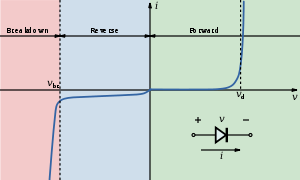
Вольт-амперная характеристика (ВАХ) — график зависимости тока через двухполюсник от напряжения на этом двухполюснике. Вольт-амперная характеристика описывает поведение двухполюсника на постоянном токе. Чаще всего рассматривают ВАХ нелинейных элементов (степень нелинейности определяется коэффициентом нелинейности  ), поскольку для линейных элементов ВАХ представляет собой прямую линию и не представляет особого интереса.
Характерные примеры элементов, обладающих существенно нелинейной ВАХ: диод, тиристор, стабилитрон.
Для трехполюсных элементов (таких, как транзистор, тиристор или ламповый триод) часто строят семейства кривых, являющимися ВАХ для двухполюсника при так или иначе заданных параметрах на третьем выводе элемента.
Необходимо отметить, что в реальной схеме, особенно работающей с относительно высокими частотами (близкими к границам рабочего частотного диапазона) для данного устройства реальная зависимость напряжения от времени может пробегать по траекториям, весьма далёким от «идеальной» ВАХ. Чаще всего это связано с ёмкостью или другими инерционными свойствами элемента.
Преобразования ВАХ
Полезно отметить некоторые свойства вольтамперных характеристик составных элементов (схем, состоящих из нескольких двухполюсников)
Параллельное соединение — при параллельном соединении двух двухполюсников, при каждом значении напряжения складываются токи, текущие через них, а при последовательном — для каждого значения тока складываются напряжения на элементах.
См. также
- Нагрузочная характеристика (электроника)
Толковый словарь русского языка. Поиск по слову, типу, синониму, антониму и описанию. Словарь ударений.
вольт-ампер
ТОЛКОВЫЙ СЛОВАРЬ
м.
Единица измерения полной мощности переменного электрического тока в Международной системе единиц.
ЭНЦИКЛОПЕДИЧЕСКИЙ СЛОВАРЬ
Вольт-ампе́р — единица СИ полной мощности электрической цепи переменного тока, то есть мощности электрической цепи при действующих значениях силы тока 1 А и напряжения 1 В. Обозначается В·А. Рассматривают также активную мощность, выражаемую в ваттах, и реактивную мощность, выражаемую в варах.
* * *
ВОЛЬТ-АМПЕР — ВОЛЬТ-АМПЕ́Р, единица СИ (см. СИ (система единиц)) полной мощности электрической цепи переменного тока, т. е. мощности электрической цепи при действующих значениях силы тока 1 А и напряжения 1 В. Обозначается В·А. Рассматривают также активную мощность, выражаемую в ваттах, и реактивную мощность, выражаемую в варах.
БОЛЬШОЙ ЭНЦИКЛОПЕДИЧЕСКИЙ СЛОВАРЬ
ВОЛЬТ-АМПЕР — единица СИ полной мощности электрической цепи переменного тока, т. е. мощности электрической цепи при действующих значениях силы тока 1 А и напряжения 1 В. Обозначается В.А. Рассматривают также активную мощность, выражаемую в ваттах, и реактивную мощность, выражаемую в варах.
СЛИТНО. РАЗДЕЛЬНО. ЧЕРЕЗ ДЕФИС
вольт-ампе/р, вольт-ампе/ра
ОРФОГРАФИЧЕСКИЙ СЛОВАРЬ
вольт-ампе́р, -а, род. п. мн. ч. -ов, счетн. ф. -ампе́р
СЛОВАРЬ УДАРЕНИЙ
во́льт-ампе́р, -а; р. мн. -ампе́р
ФОРМЫ СЛОВ
во́льт-ампе́р, во́льт-ампе́ры, во́льт-ампе́ра, во́льт-ампе́ру, во́льт-ампе́рам, во́льт-ампе́ром, во́льт-ампе́рами, во́льт-ампе́ре, во́льт-ампе́рах
СИНОНИМЫ
сущ., кол-во синонимов: 1
МОРФЕМНО-ОРФОГРАФИЧЕСКИЙ СЛОВАРЬ
СЛОВАРЬ ГАЛЛИЦИЗМОВ РУССКОГО ЯЗЫКА
ВОЛЬТ-АМПЕР а, м. voltampère m. Единица измерения полной мощности переменного электрического тока в Международной системе единиц. БАС-2. Вольтамперный ая, ое. В тихом разряде эта вольтамперная харктеристика является отрицательной. Природа 1937 9 15. — Лекс. ТЭ 1928: вольт-ампер; БСЭ-2: вольт-ампе/р.
СЛОВАРЬ ИНОСТРАННЫХ СЛОВ
Практическая единица силы электрического тока, т. е. работы, производимой им в единицу времени.
ПОЛЕЗНЫЕ СЕРВИСЫ
вольт-амперная характеристика
ЭНЦИКЛОПЕДИЧЕСКИЙ СЛОВАРЬ
Вольт-ампе́рная характери́стика — зависимость напряжения от тока (или тока от напряжения) на участке электрической цепи; выражается обычно в виде графика или таблицы.
* * *
ВОЛЬТ-АМПЕРНАЯ ХАРАКТЕРИСТИКА — ВОЛЬТ-АМПЕ́РНАЯ ХАРАКТЕРИ́СТИКА, зависимость напряжения от тока (или тока от напряжения) на участке электрической цепи; выражается обычно в виде графика или таблицы.
БОЛЬШОЙ ЭНЦИКЛОПЕДИЧЕСКИЙ СЛОВАРЬ
ВОЛЬТ-АМПЕРНАЯ ХАРАКТЕРИСТИКА — зависимость напряжения от тока (или тока от напряжения) на участке электрической цепи; выражается обычно в виде графика или таблицы.
ПОЛЕЗНЫЕ СЕРВИСЫ
вольт-амперный
СЛИТНО. РАЗДЕЛЬНО. ЧЕРЕЗ ДЕФИС
ОРФОГРАФИЧЕСКИЙ СЛОВАРЬ
МОРФЕМНО-ОРФОГРАФИЧЕСКИЙ СЛОВАРЬ
ПОЛЕЗНЫЕ СЕРВИСЫ
From Wikipedia, the free encyclopedia
(Redirected from I-v curve)

A current–voltage characteristic or I–V curve (current–voltage curve) is a relationship, typically represented as a chart or graph, between the electric current through a circuit, device, or material, and the corresponding voltage, or potential difference across it.
In electronics[edit]

MOSFET drain current vs. drain-to-source voltage for several values of the overdrive voltage,  ; the boundary between linear (ohmic) and saturation (active) modes is indicated by the upward curving parabola.
In electronics, the relationship between the direct current (DC) through an electronic device and the DC voltage across its terminals is called a current–voltage characteristic of the device. Electronic engineers use these charts to determine basic parameters of a device and to model its behavior in an electrical circuit. These characteristics are also known as I–V curves, referring to the standard symbols for current and voltage.
In electronic components with more than two terminals, such as vacuum tubes and transistors, the current-voltage relationship at one pair of terminals may depend on the current or voltage on a third terminal. This is usually displayed on a more complex current–voltage graph with multiple curves, each one representing the current-voltage relationship at a different value of current or voltage on the third terminal.[1]
For example the diagram at right shows a family of I–V curves for a MOSFET as a function of drain voltage with overvoltage (VGS − Vth) as a parameter.
The simplest I–V curve is that of a resistor, which according to Ohm’s law exhibits a linear relationship between the applied voltage and the resulting electric current; the current is proportional to the voltage, so the I–V curve is a straight line through the origin with positive slope. The reciprocal of the slope is equal to the resistance.
The I–V curve of an electrical component can be measured with an instrument called a curve tracer. The transconductance and Early voltage of a transistor are examples of parameters traditionally measured from the device’s I–V curve.
Types of I–V curves[edit]
The shape of an electrical component’s characteristic curve reveals much about its operating properties. I–V curves of different devices can be grouped into categories:

The quadrants of the I–V plane. Power sources have curves passing through the red regions.
- Active vs passive: Devices which have I–V curves which are limited to the first and third quadrants of the I–V plane, passing through the origin, are passive components (loads), that consume electric power from the circuit. Examples are resistors and electric motors. Conventional current always flows through these devices in the direction of the electric field, from the positive voltage terminal to the negative, so the charges lose potential energy in the device, which is converted to heat or some other form of energy.
- In contrast, devices with I–V curves which pass through the second or fourth quadrants are active components, power sources, which can produce electric power. Examples are batteries and generators. When it is operating in the second or fourth quadrant, current is forced to flow through the device from the negative to the positive voltage terminal, against the opposing force of the electric field, so the electric charges are gaining potential energy. Thus the device is converting some other form of energy into electric energy.
- Linear vs nonlinear: A straight line through the origin represents a linear circuit element, while a curved line represents a nonlinear element. For example, resistors, capacitors, and inductors are linear, while diodes and transistors are nonlinear. An I–V curve which is a straight line through the origin with positive slope represents a linear or ohmic resistor, the most common type of resistance encountered in circuits. It obeys Ohm’s law; the current is proportional to the applied voltage over a wide range. Its resistance, equal to the reciprocal of the slope of the line, is constant. A curved I–V line represents a nonlinear resistance, such as a diode. In this type the resistance varies with the applied voltage or current.
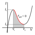
- Negative resistance vs positive resistance: If the I–V curve has a positive slope (increasing to the right) throughout, it represents a positive resistance. An I–V curve that is nonmonotonic (having peaks and valleys) represents a device which has negative resistance. Regions of the curve which have a negative slope (declining to the right) represent operating regions where the device has negative differential resistance, while regions of positive slope represent positive differential resistance. Negative resistance devices can be used to make amplifiers and oscillators. Tunnel diodes and Gunn diodes are examples of components that have negative resistance.
- Hysteresis vs single-valued: Devices which have hysteresis; that is, in which the current-voltage relation depends not only on the present applied input but also on the past history of inputs, have I–V curves consisting of families of closed loops. Each branch of the loop is marked with a direction represented by an arrow. Examples of devices with hysteresis include iron-core inductors and transformers, thyristors such as SCRs and DIACs, and gas-discharge tubes such as neon lights.
-

I–V curve similar to a tunnel diode characteristic curve. It has negative resistance in the shaded voltage region, between v1 and v2
-

DIAC I–V curve. VBO is the breakover voltage.
-

Gunn diode I–V curve, showing negative differential resistance with hysteresis (notice arrows)


In electrophysiology[edit]

An approximation of the potassium and sodium ion components of a so-called «whole cell» I–V curve of a neuron.
While I–V curves are applicable to any electrical system, they find wide use in the field of biological electricity, particularly in the sub-field of electrophysiology. In this case, the voltage refers to the voltage across a biological membrane, a membrane potential, and the current is the flow of charged ions through channels in this membrane. The current is determined by the conductances of these channels.
In the case of ionic current across biological membranes, currents are measured from inside to outside. That is, positive currents, known as «outward current», corresponding to positively charged ions crossing a cell membrane from the inside to the outside, or a negatively charged ion crossing from the outside to the inside. Similarly, currents with a negative value are referred to as «inward current», corresponding to positively charged ions crossing a cell membrane from the outside to the inside, or a negatively charged ion crossing from inside to outside.
The figure to the right shows an I–V curve that is more relevant to the currents in excitable biological membranes (such as a neuronal axon).
The blue line shows the I–V relationship for the potassium ion. Note that it is linear, indicating no voltage-dependent gating of the potassium ion channel. The yellow line shows the I–V relationship for the sodium ion. Note that it is not linear, indicating that the sodium ion channel is voltage-dependent. The green line indicates the I–V relationship derived from summing the sodium and potassium currents. This approximates the actual membrane potential and current relationship of a cell containing both types of channel.
See also[edit]
- Maximum power point tracking
- Voltammetry
References[edit]
- ^ H. J. van der Bijl (1919). «Theory and Operating Characteristics of the Themionic Amplifier». Proceedings of the IRE. Institute of Radio Engineers. 7 (2): 97–126. doi:10.1109/JRPROC.1919.217425.
From Wikipedia, the free encyclopedia
(Redirected from I-v curve)
A current–voltage characteristic or I–V curve (current–voltage curve) is a relationship, typically represented as a chart or graph, between the electric current through a circuit, device, or material, and the corresponding voltage, or potential difference across it.
In electronics[edit]
MOSFET drain current vs. drain-to-source voltage for several values of the overdrive voltage, ; the boundary between linear (ohmic) and saturation (active) modes is indicated by the upward curving parabola.
In electronics, the relationship between the direct current (DC) through an electronic device and the DC voltage across its terminals is called a current–voltage characteristic of the device. Electronic engineers use these charts to determine basic parameters of a device and to model its behavior in an electrical circuit. These characteristics are also known as I–V curves, referring to the standard symbols for current and voltage.
In electronic components with more than two terminals, such as vacuum tubes and transistors, the current-voltage relationship at one pair of terminals may depend on the current or voltage on a third terminal. This is usually displayed on a more complex current–voltage graph with multiple curves, each one representing the current-voltage relationship at a different value of current or voltage on the third terminal.[1]
For example the diagram at right shows a family of I–V curves for a MOSFET as a function of drain voltage with overvoltage (VGS − Vth) as a parameter.
The simplest I–V curve is that of a resistor, which according to Ohm’s law exhibits a linear relationship between the applied voltage and the resulting electric current; the current is proportional to the voltage, so the I–V curve is a straight line through the origin with positive slope. The reciprocal of the slope is equal to the resistance.
The I–V curve of an electrical component can be measured with an instrument called a curve tracer. The transconductance and Early voltage of a transistor are examples of parameters traditionally measured from the device’s I–V curve.
Types of I–V curves[edit]
The shape of an electrical component’s characteristic curve reveals much about its operating properties. I–V curves of different devices can be grouped into categories:
The quadrants of the I–V plane. Power sources have curves passing through the red regions.
- Active vs passive: Devices which have I–V curves which are limited to the first and third quadrants of the I–V plane, passing through the origin, are passive components (loads), that consume electric power from the circuit. Examples are resistors and electric motors. Conventional current always flows through these devices in the direction of the electric field, from the positive voltage terminal to the negative, so the charges lose potential energy in the device, which is converted to heat or some other form of energy.
- In contrast, devices with I–V curves which pass through the second or fourth quadrants are active components, power sources, which can produce electric power. Examples are batteries and generators. When it is operating in the second or fourth quadrant, current is forced to flow through the device from the negative to the positive voltage terminal, against the opposing force of the electric field, so the electric charges are gaining potential energy. Thus the device is converting some other form of energy into electric energy.
- Linear vs nonlinear: A straight line through the origin represents a linear circuit element, while a curved line represents a nonlinear element. For example, resistors, capacitors, and inductors are linear, while diodes and transistors are nonlinear. An I–V curve which is a straight line through the origin with positive slope represents a linear or ohmic resistor, the most common type of resistance encountered in circuits. It obeys Ohm’s law; the current is proportional to the applied voltage over a wide range. Its resistance, equal to the reciprocal of the slope of the line, is constant. A curved I–V line represents a nonlinear resistance, such as a diode. In this type the resistance varies with the applied voltage or current.
- Negative resistance vs positive resistance: If the I–V curve has a positive slope (increasing to the right) throughout, it represents a positive resistance. An I–V curve that is nonmonotonic (having peaks and valleys) represents a device which has negative resistance. Regions of the curve which have a negative slope (declining to the right) represent operating regions where the device has negative differential resistance, while regions of positive slope represent positive differential resistance. Negative resistance devices can be used to make amplifiers and oscillators. Tunnel diodes and Gunn diodes are examples of components that have negative resistance.
- Hysteresis vs single-valued: Devices which have hysteresis; that is, in which the current-voltage relation depends not only on the present applied input but also on the past history of inputs, have I–V curves consisting of families of closed loops. Each branch of the loop is marked with a direction represented by an arrow. Examples of devices with hysteresis include iron-core inductors and transformers, thyristors such as SCRs and DIACs, and gas-discharge tubes such as neon lights.
-
I–V curve similar to a tunnel diode characteristic curve. It has negative resistance in the shaded voltage region, between v1 and v2
-
DIAC I–V curve. VBO is the breakover voltage.
-
Gunn diode I–V curve, showing negative differential resistance with hysteresis (notice arrows)
In electrophysiology[edit]
An approximation of the potassium and sodium ion components of a so-called «whole cell» I–V curve of a neuron.
While I–V curves are applicable to any electrical system, they find wide use in the field of biological electricity, particularly in the sub-field of electrophysiology. In this case, the voltage refers to the voltage across a biological membrane, a membrane potential, and the current is the flow of charged ions through channels in this membrane. The current is determined by the conductances of these channels.
In the case of ionic current across biological membranes, currents are measured from inside to outside. That is, positive currents, known as «outward current», corresponding to positively charged ions crossing a cell membrane from the inside to the outside, or a negatively charged ion crossing from the outside to the inside. Similarly, currents with a negative value are referred to as «inward current», corresponding to positively charged ions crossing a cell membrane from the outside to the inside, or a negatively charged ion crossing from inside to outside.
The figure to the right shows an I–V curve that is more relevant to the currents in excitable biological membranes (such as a neuronal axon).
The blue line shows the I–V relationship for the potassium ion. Note that it is linear, indicating no voltage-dependent gating of the potassium ion channel. The yellow line shows the I–V relationship for the sodium ion. Note that it is not linear, indicating that the sodium ion channel is voltage-dependent. The green line indicates the I–V relationship derived from summing the sodium and potassium currents. This approximates the actual membrane potential and current relationship of a cell containing both types of channel.
See also[edit]
- Maximum power point tracking
- Voltammetry
References[edit]
- ^ H. J. van der Bijl (1919). «Theory and Operating Characteristics of the Themionic Amplifier». Proceedings of the IRE. Institute of Radio Engineers. 7 (2): 97–126. doi:10.1109/JRPROC.1919.217425.
Что такое вольт-амперная характеристика (ВАХ)
ВАХ — это вольт-амперная характеристика, а если точнее, зависимость тока от напряжения в каком-либо радиоэлементе. Это может быть резистор, диод, транзистор и другие радиоэлементы. Так как транзистор имеет более двух выводов, то он имеет множество ВАХ.
Думаю, не все, кто читает эту статью, хорошо учились в школе. Поэтому, давайте разберемся, что представляет из себя зависимость одной величины от другой. Как вы помните из школы, мы строили графики зависимости игрек (У) от икс (Х). Та переменная, которая зависит от другой переменной, мы откладывали по вертикали, а та, которая независима — по горизонтали. В результате у нас получалась система отображения зависимости «У» от «Х»:

Так вот, мои дорогие читатели, в электронике, чтобы описать зависимость тока от напряжения, вместо «У» у нас будет сила тока, а вместо Х — напряжение. И система отображения у нас примет вот такой вид:

Именно в такой системе координат мы будет чертить вольт-амперную характеристику. И начнем с самого распространенного радиоэлемента — резистора.
ВАХ резистора
Для того, чтобы начертить этот график, нам потребуется пропускать через резистор напряжение и смотреть соответствующее значение силы тока тока. С помощью крутилки я добавляю напряжение и записываю значения силы тока для каждого значения напряжения. Для этого берем блок питания, резистор и начинаем делать замеры:
Вот у нас появилась первая точка на графике. U=0,I=0.

Вторая точка: U=2.6, I=0.01

Третья точка: U=4.4, I=0.02

Четвертая точка: U=6.2, I=0.03

Пятая точка: U=7.9, I=0.04

Шестая точка: U=9.6, I=0.05

Седьмая точка: U=11.3, I=0.06

Восьмая точка: U=13, I=0.07

Девятая точка: U=14.7, I=0.08

Давайте построим график по этим точкам:

Да у нас получилась почти прямая линия! То, что она чуть кривая, связана с погрешностью измерений и погрешностью самого прибора. Следовательно, так как у нас получилась прямая линия, то значит такие элементы, как резисторы называются элементами с линейной ВАХ.
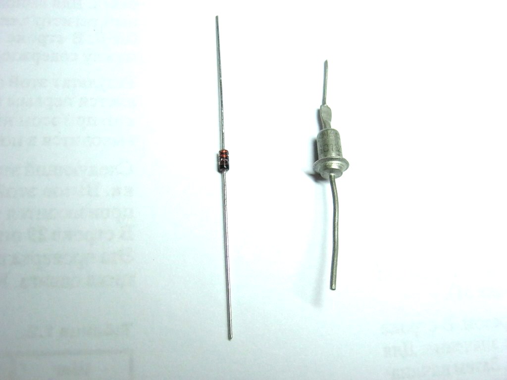
ВАХ диода
Как вы знаете, диод пропускает электрический ток только в одном направлении. Это свойство диода мы используем в диодных мостах, а также для проверки диода мультиметром. Давайте построим ВАХ для диода. Берем блок питания, цепляем его к диоду (плюс на анод, минус на катод) и начинаем точно также делать замеры.
Первая точка: U=0,I=0.

Вторая точка: U=0.4, I=0.

Третья точка: U=0.6, I=0.01

Четвертая точка: U=0.7, I=0.03

Пятая точка: U=0.8,I=0.06

Шестая точка: U=0.9, I=0.13

Седьмая точка: U=1, I=0.37

Строим график по полученным значениям:

Ничего себе загибулина :-). Вот это и есть вольт-амперная характеристика диода. На графике мы не видим прямую линию, поэтому такая вольт-амперная характеристика называется НЕлинейной. Для кремниевых диодов она начинается со значения 0,5-0,7 Вольт. Для германиевых диодов ВАХ начинается со значения 0,3-0,4 Вольт.
ВАХ стабилитрона
Стабилитроны работают в режиме лавинного пробоя. Выглядят они также, как и диоды.
Мы подключаем стабилитрон как диод в обратном направлении: на анод минус, а на катод — плюс. В результате, напряжение на стабилитроне остается почти таким же, а сила тока может меняться в зависимости от подключаемой нагрузки на стабилитроне. Как говорят электронщики, мы используем в стабилитроне обратную ветвь ВАХ.

Рекомендуем посмотреть видео материал на эту тему:
Значение слова «ВОЛЬТАМПЕРНАЯ ХАРАКТЕРИСТИКА» найдено в 28 источниках
ВОЛЬТАМПЕРНАЯ ХАРАКТЕРИСТИКА
зависимость напряжения от тока или тока от напряжения на участке электрической цепи. В. х. может изображаться аналитически — как функция V = f (I), где V — напряжение, I — ток; графически — в виде линии в системе координат (V, I), например, анодная характеристика электровакуумных ламп.
ВОЛЬТАМПЕРНАЯ ХАРАКТЕРИСТИКА, зависимость
напряжения от тока или тока от напряжения на участке электрич. цепи. В.
х. может изображаться аналитически — как функция V = f(I), где
V
— напряжение, 1 — ток; графически — в виде линии в системе координат
(V, I), напр, анодная характеристика электровакуумных ламп.
зависимость тока от приложенного к элементу электрич. цепи напряжения или зависимость падения напряжения на элементе электрич. цепи от протекающего через него тока. Если сопротивление элемента не зависит от тока, то В.-а. х.—прямая линия, проходящая через начало координат. В.-а. х. нелинейных элементов электрич. цепи (электровакуумные, газоразрядные и твёрдотельные приборы) имеют нелинейные участки и разнообразную форму (N-образные В.-а. х., S-образные и т. п.).
Физический энциклопедический словарь. — М.: Советская энциклопедия..1983.
anode characteristic, current-voltage characteristic, diode characteristic, E-I characteristic, voltage-current characteristic, current-voltage curve, current-voltage diagram, volt-amps diagram
* * *
volt-ampere characteristic
«…Вольт-амперная характеристика — зависимость электрического напряжения на выводах элемента электрической цепи от электрического тока в нем…»
Источник:
«ЭЛЕКТРОТЕХНИКА . ТЕРМИНЫ И ОПРЕДЕЛЕНИЯ ОСНОВНЫХ ПОНЯТИЙ. ГОСТ Р 52002-2003»
(утв. Постановлением Госстандарта РФ от 09.01.2003 N 3-ст)
1. Зависимость электрического напряжения на выводах элемента электрической цепи от электрического тока в нем Употребляется в документе:
ГОСТ Р 52002-2003 Электротехника. Термины и определения основных понятий
Телекоммуникационный словарь.2013.
зависимость электрич. напряжения от тока (или тока от напряжения) на участке электрич. цепи или в её отд. элементе (резисторе, ПП диоде и т. д.). У линейных элементов электрич. цепи В. х. — прямая линия.
I-U-Charakteristik, I-U-Kennlinie, Spannungs-Strom-Charakteristik, Strom-Spannungs-Kennlinie, Strom-Spannungs-Verhalten, U-I-Kennlinie, Voltamperecharakteristik
ВОЛЬТ-АМПЕРНАЯ ХАРАКТЕРИСТИКА, зависимость напряжения от тока (или тока от напряжения) на участке электрической цепи; выражается обычно в виде графика или таблицы.
ВОЛЬТ-АМПЕРНАЯ ХАРАКТЕРИСТИКА — зависимость напряжения от тока (или тока от напряжения) на участке электрической цепи; выражается обычно в виде графика или таблицы.
ВОЛЬТ-АМПЕРНАЯ ХАРАКТЕРИСТИКА , зависимость напряжения от тока (или тока от напряжения) на участке электрической цепи; выражается обычно в виде графика или таблицы.
caractéristique f courant-tension, caractéristique f tension-courant; courbe f caractéristique du tube électronique
ВОЛЬТ-АМПЕРНАЯ ХАРАКТЕРИСТИКА, зависимость напряжения от тока (или тока от напряжения) на участке электрической цепи; выражается обычно в виде графика или таблицы.
зависимость напряжения от тока (или тока от напряжения) на участке электрич. цепи; выражается обычно в виде графика или таблицы.
— зависимость напряжения от тока (или токаот напряжения) на участке электрической цепи; выражается обычно в видеграфика или таблицы.
(тиристора) anode characteristic, current-voltage characteristic, volt-ampere characteristic, current-voltage curve, i-v curve, IV
Spannung-Strom-Charakteristik, Stromspannungskennlinie, Voltampercharakteristik
caratteristica tensione-corrente
volt-ampere characteristic, current-voltage characteristic
(тиристора) anode-to-cathode voltage-current characteristic
voltage-current characteristic
volt-ampere characteristic
вольт-ампе́рна характери́стика
caractéristique voltampère